Assembling The Base
Click on the images to embiggen.
Legs
- The leg lengths come from the cut calculator.
- Do whatever it takes to get the legs as equal in length as possible. This will really help in leveling and keeping it level.
- In this picture, the one on the far left is too short, so it could either be shimmed during assembly or sand/grind the other legs.
- A little extra time here pays off for the life of the machine.
Tip
Sand, grind, or file the inside and outside edges of all the cuts on the rails and legs. This prevents cut wires and eases assembly.
Tools
- 8mm Socket or nut driver
- Phillips #2 Screwdriver
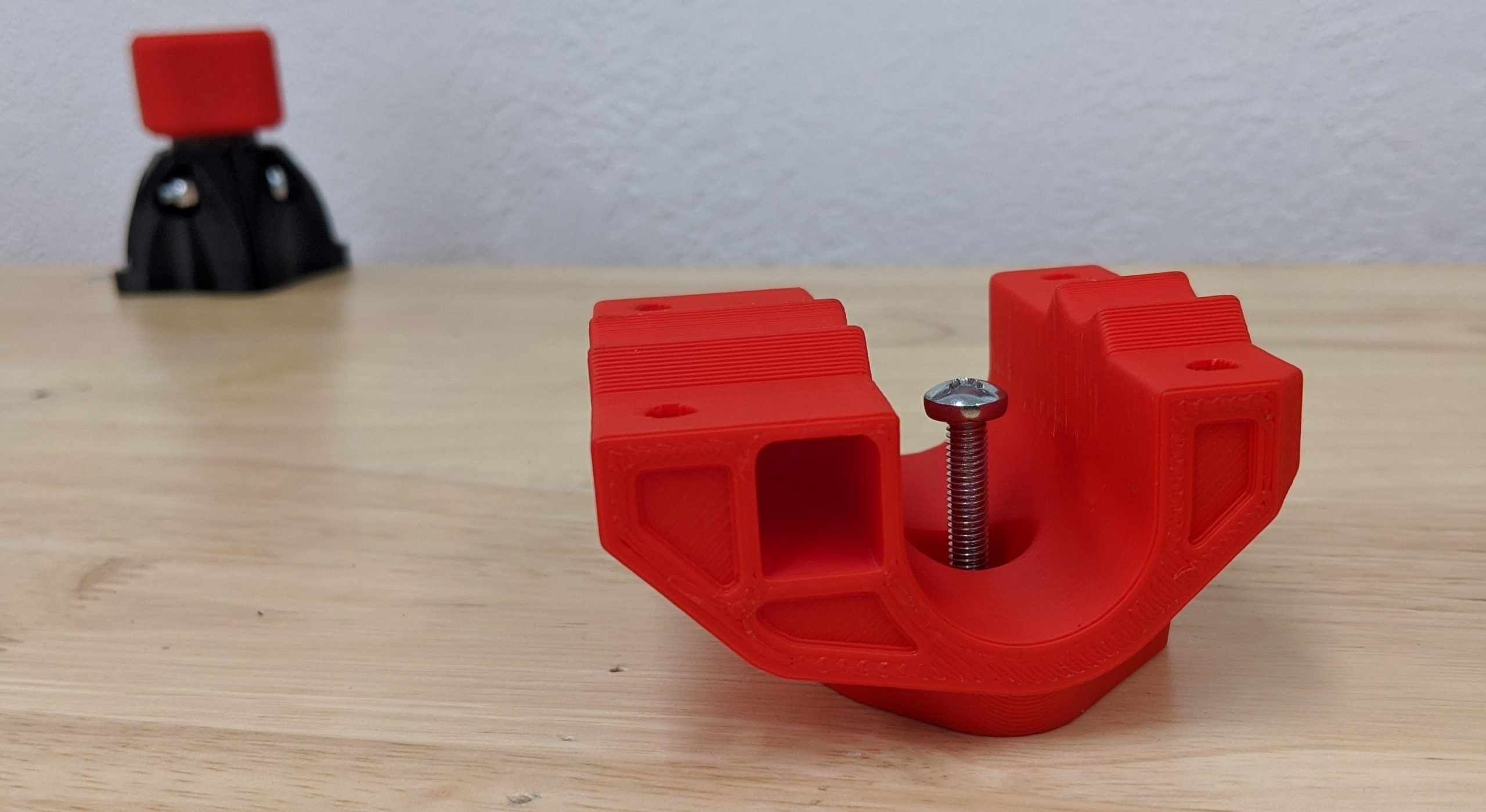
Legs and Feet
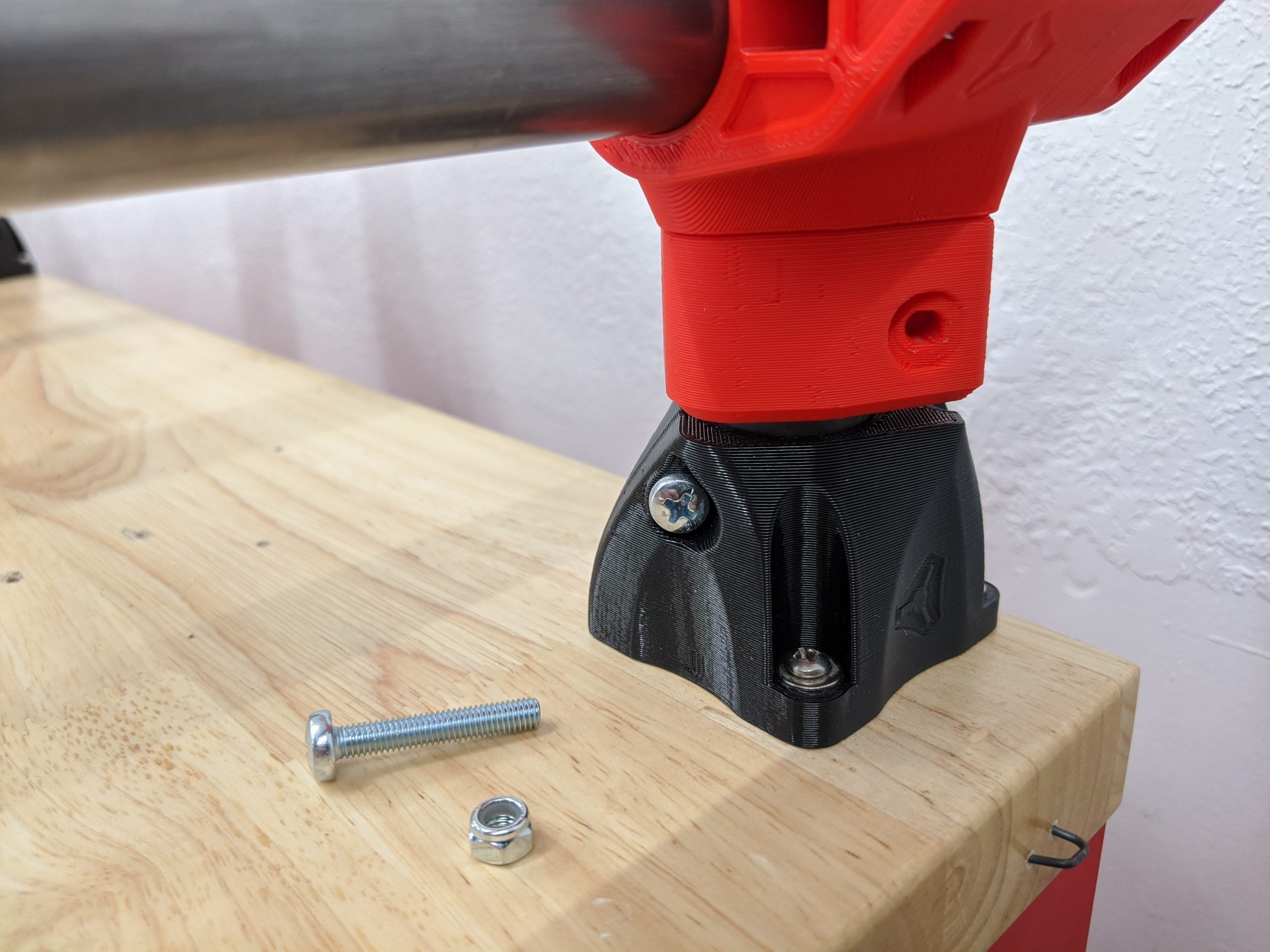
- You will need the legs, printed feet, M5x30 screws and locknuts.
Tip
It is best to pre-thread all the locknuts before assembly. This will loosen them and prevent mangling of the printed parts.
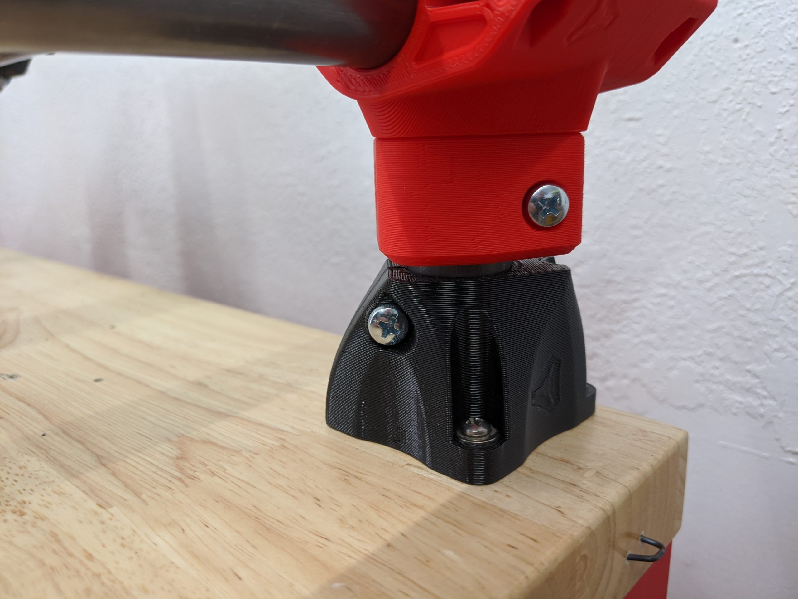
- Insert the leg and make sure it is seated all the way to the table.
- The feet have a small side for the head of the screw and a larger opening for the nut and socket.
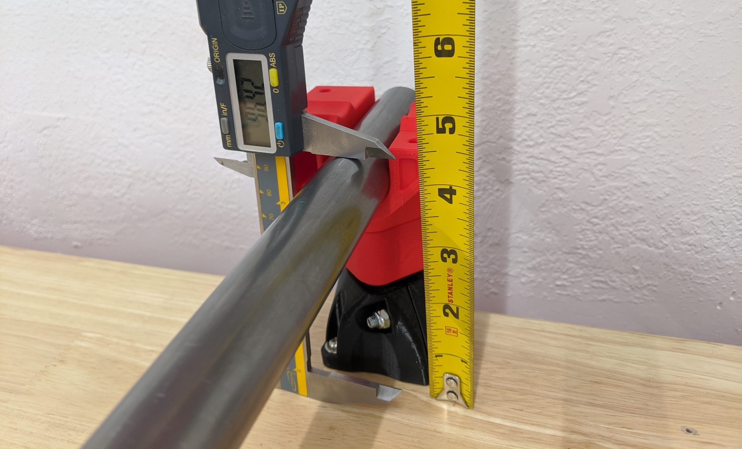
- Snug this screw. Snug means just a ¼ turn past the nut making contact. This does not need to be super tight.
- There is a 2+mm gap here, do not try to close the gap.
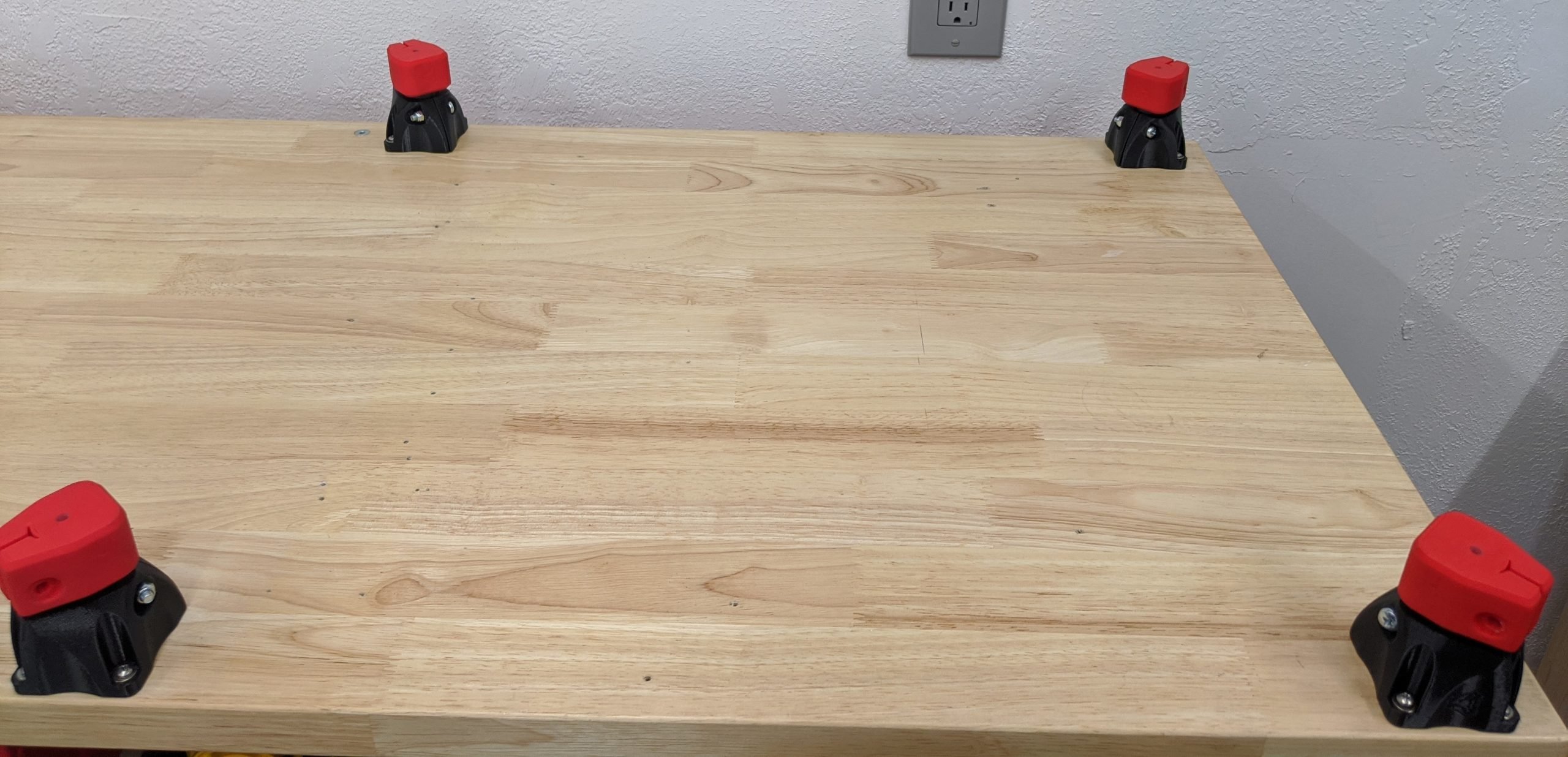
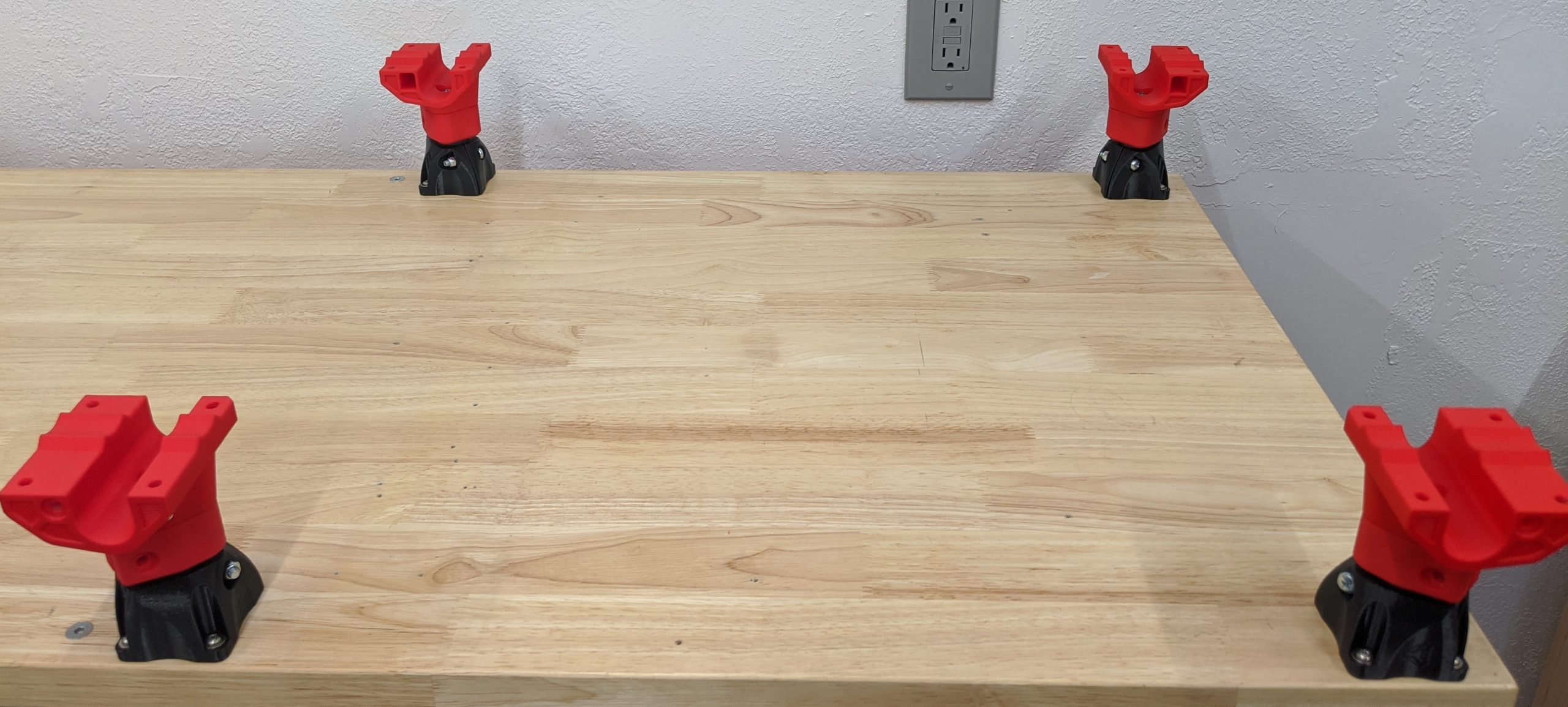
Base Layout
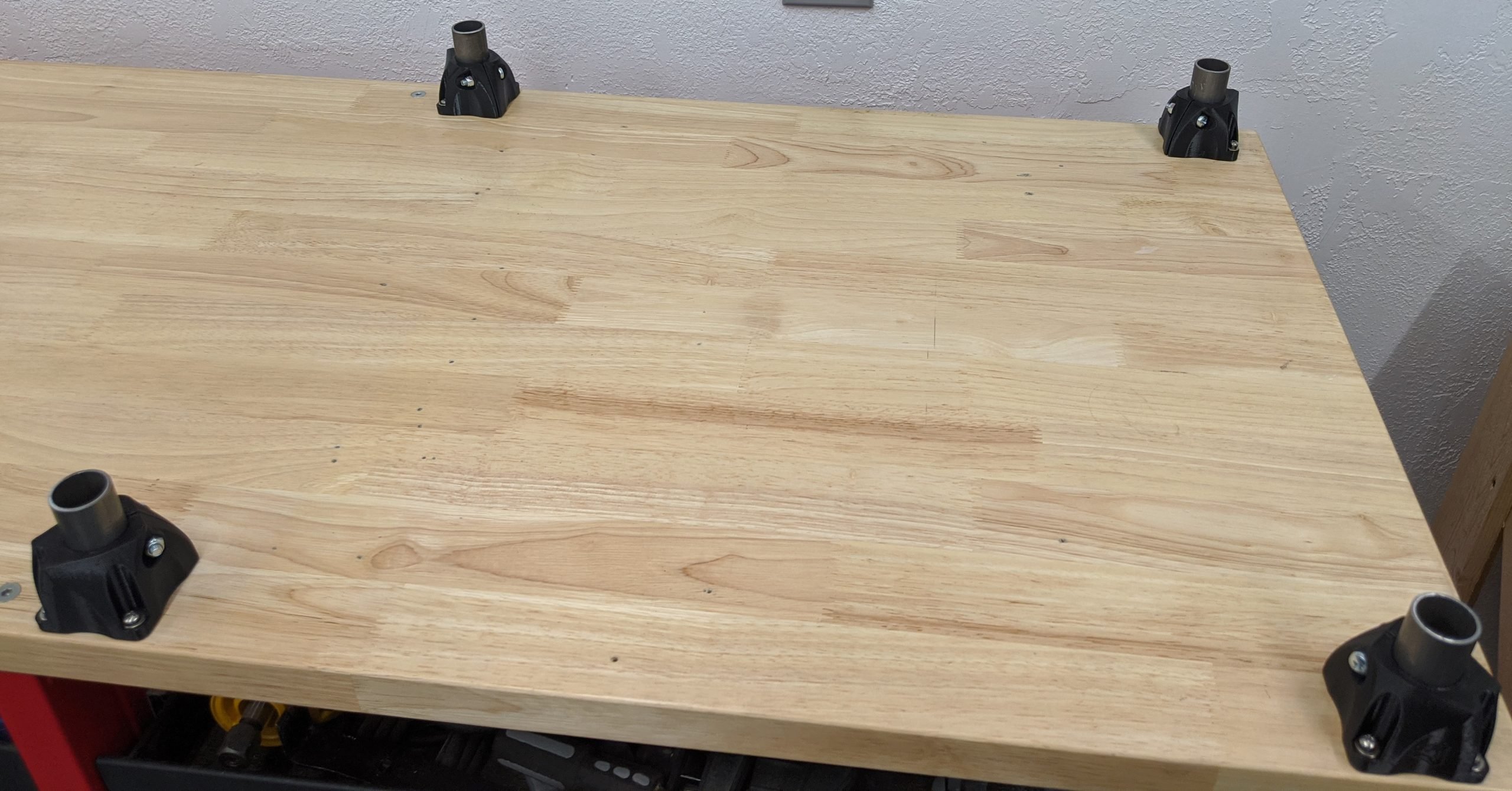
- Use whatever screws are appropriate for your table, these are not included in the V1 Kits.
- Layout the foot assemblies on your table according to the dimensions from the cut calculator.
- Notice all the clamping screws are oriented towards the center of the build area.
- Screw down the two assemblies along the front edge of the table. These will be your fixed references.
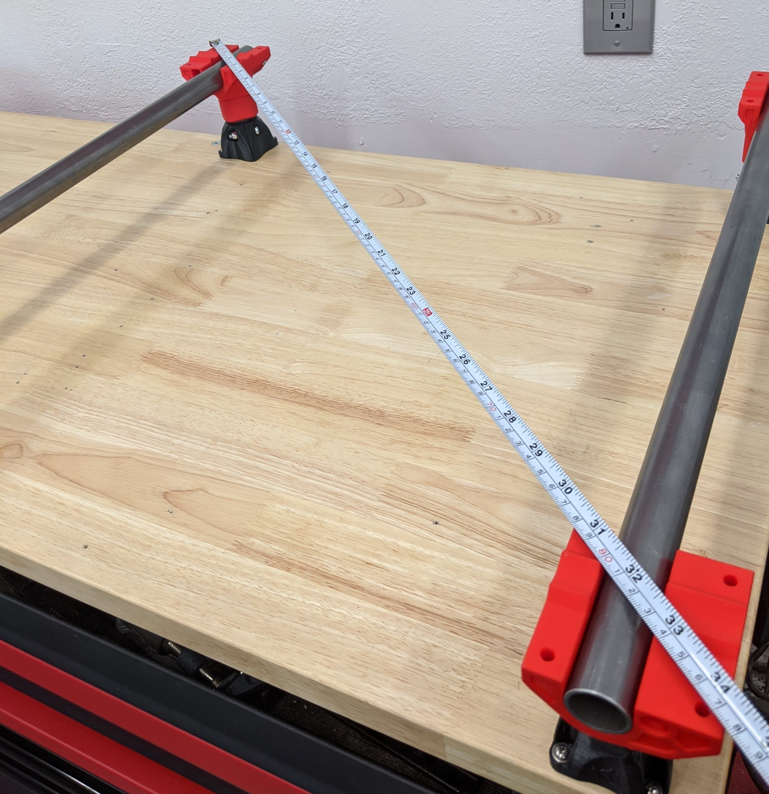
- Measure as carefully and accurately as you can across the leg tops. Your machine can only be as accurate as you build it.
- Validate that the front length exactly matches the back length, and that the left and right lengths match.
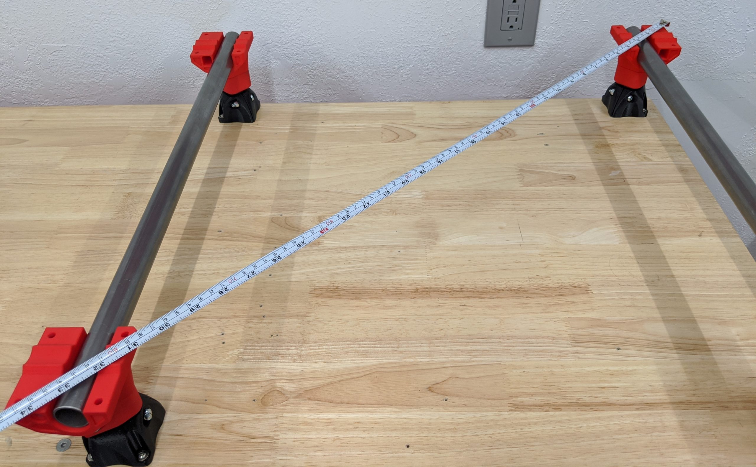
- Measure diagonally across the leg tops.
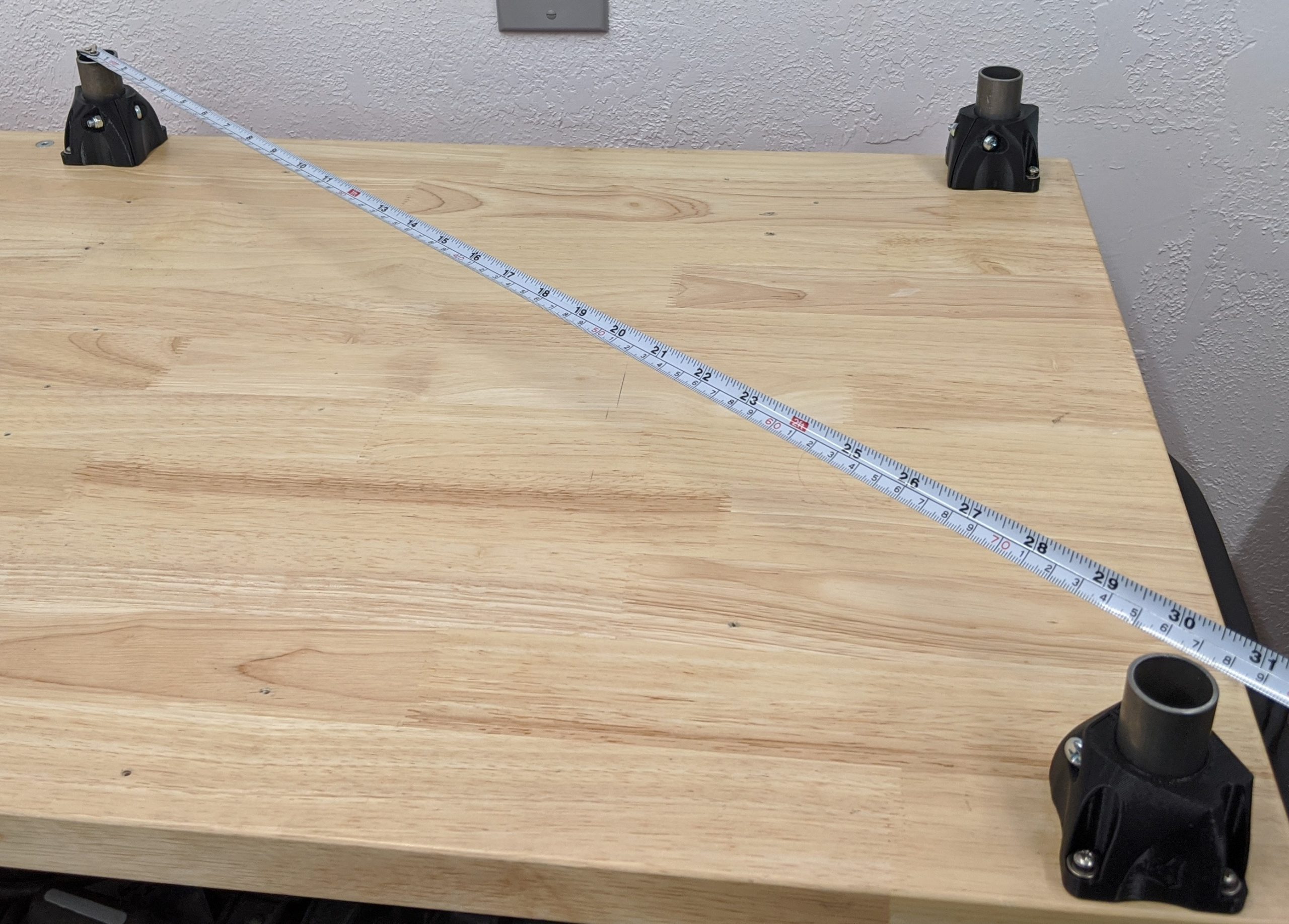
- Compare this measurement to the next one.
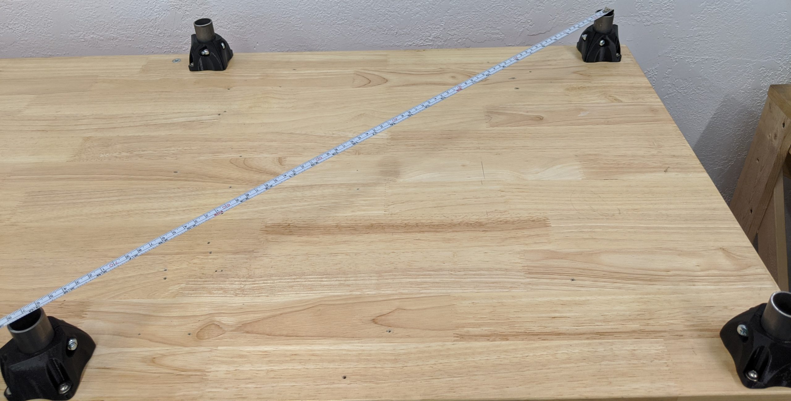
- This next diagonal should match the previous one. Squaring this way can be extremely accurate because any error in the leg locations is multiplied in this measurement.
- Adjust both rear legs until you are satisfied with the precision.
- Screw in one foot at a time, minor adjustments are possible.
- Triple check the diagonals - they need to be as close as you can get them.
Tip
Marking and pre-drilling the foot hold downs in the center of the screw slots makes it much easier to get a square base. It allows a tiny bit of room for adjustment.
Leg Locks
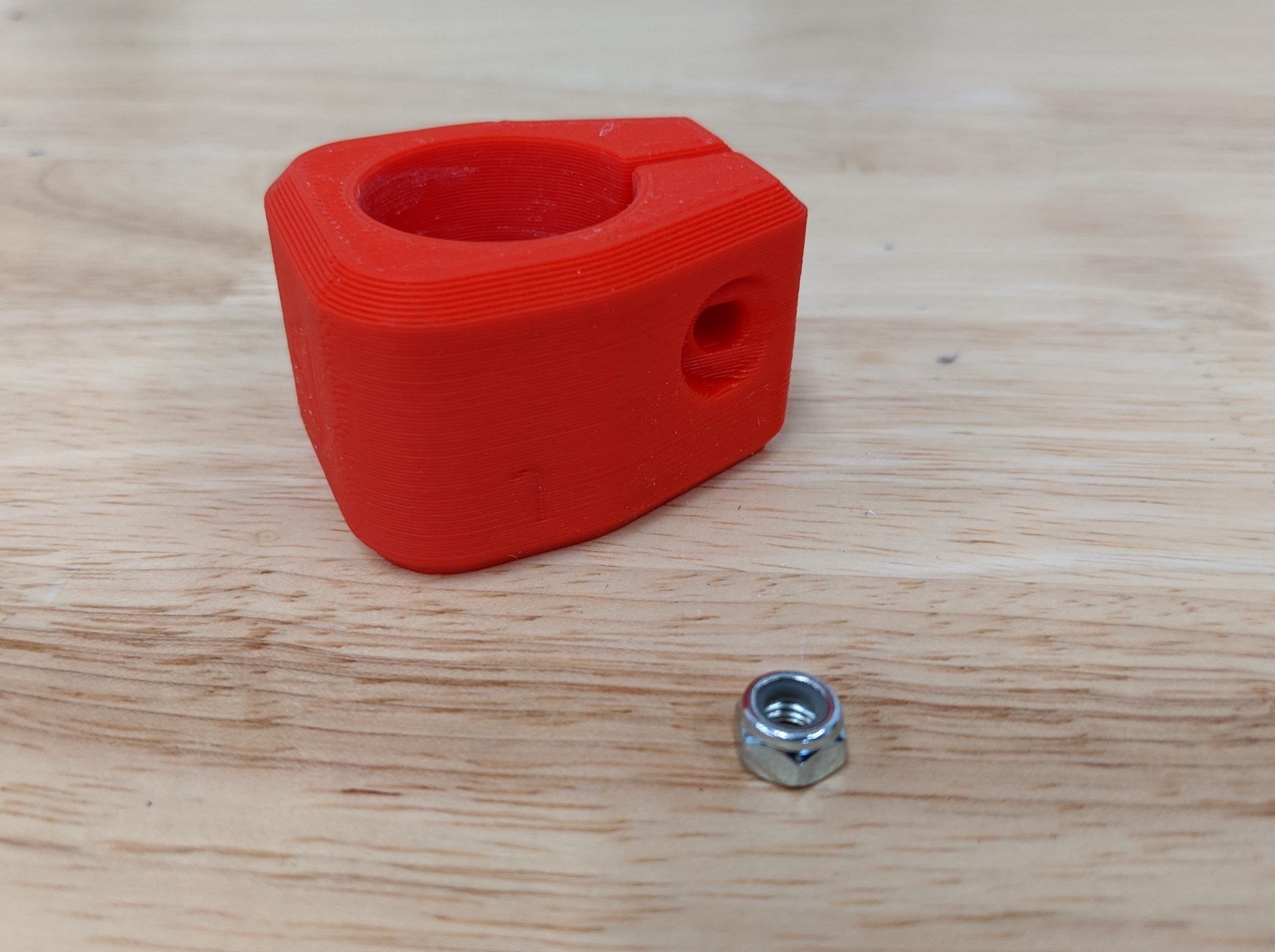
- You will need the printed Corner Leg Locks and M5 locknuts.
- It is best to pre-thread all the locknuts before assembly. This will loosen them and prevent mangling of the printed parts.
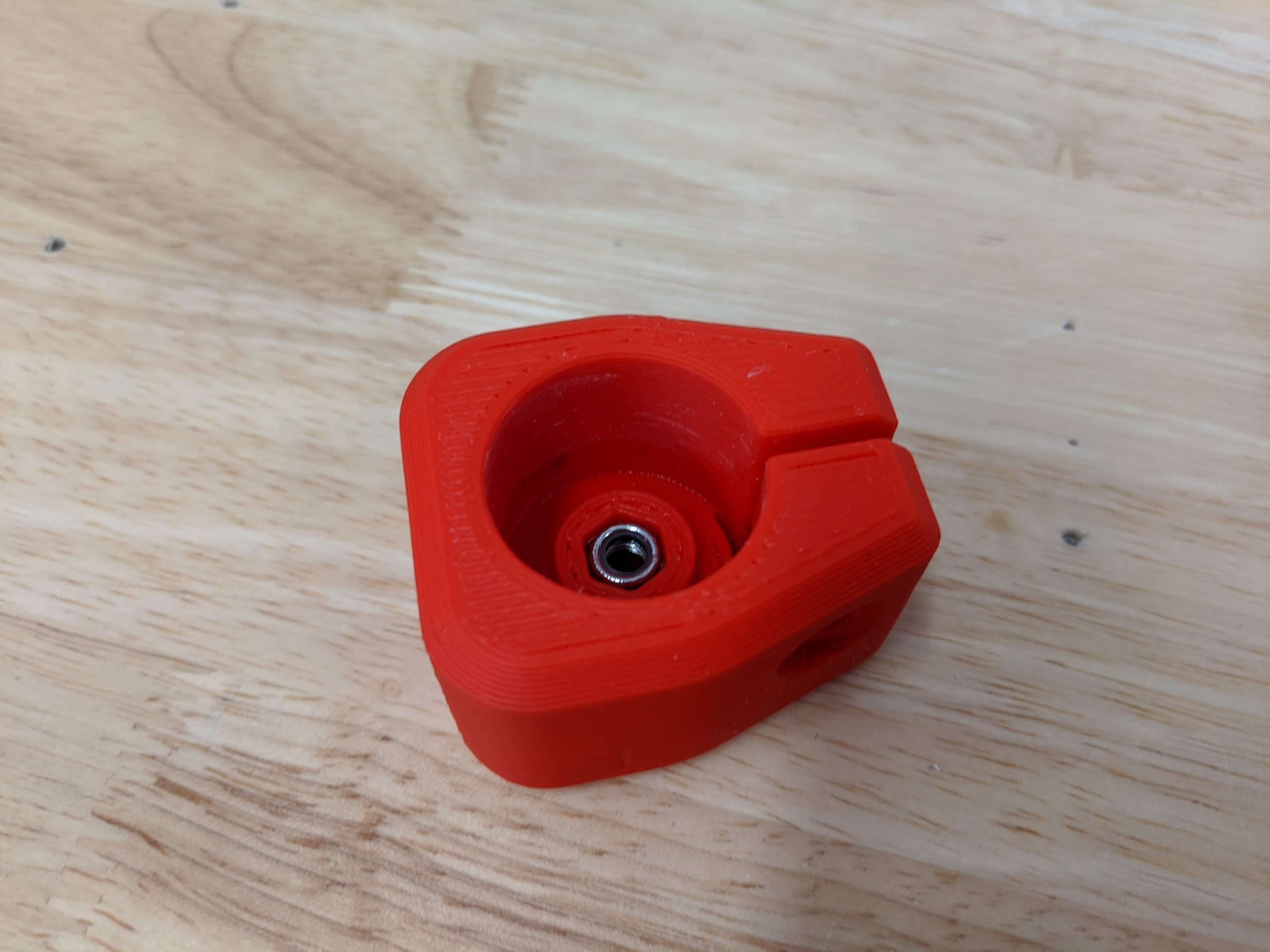
-
Push the nut into the Corner Leg Lock and fully seat it. If it does not stay on its own you can use a drop of glue.
-
If the nut does not stay on its own, you can attach the Corner Bottom very loosely with its bolt.
- Fully seat the Corner Leg Locks onto the legs.
- Orient to match the Feet below.
- Do not lock/clamp them.
Corner Bottoms
- You will need the printed Corner Bottoms and Corner Bottom Mirrored and M5x30 screws.
Warning
If you are not using the V1 Kit, please make sure your screw heads are low profile enough not to interfere with the Lower Rail.
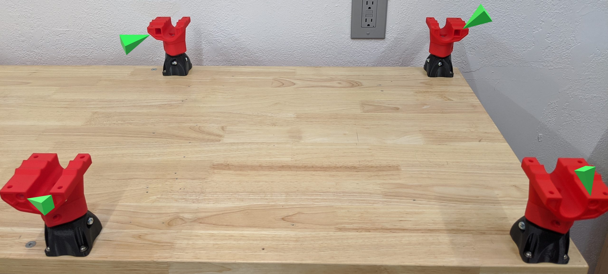
- The Corner Bottoms go on the Leg Locks as shown. Pay attention to how the belt slider slots are oriented. They point towards each other on the outside of the build area.
- This picture is taken with the 0,0 (home) corner in the bottom nearest left. The corners should be as shown.
- Get the screws started to hold the Leg Locks and Corner Bottoms together.
- Leave them loose, just tight enough to make the screw head clear the rail.
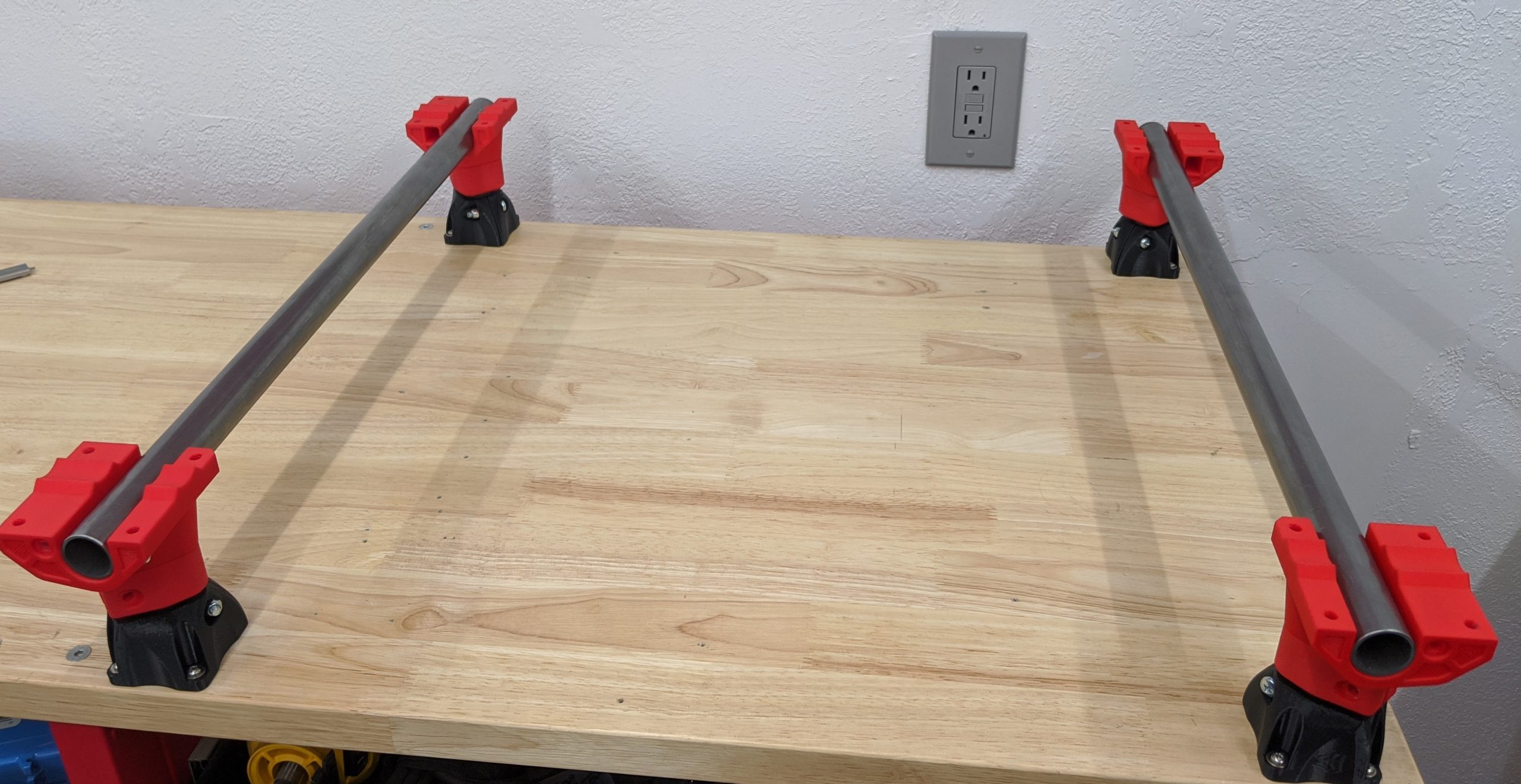
- Temporarily adding the Y rails will align the corners.
Lock The Legs
- You will need four sets of the M5 screws and locknuts.
- It is best to pre-thread all the locknuts before assembly. This will loosen them and prevent mangling of the printed parts.
- Snug up all four Leg Locks.
- Snug is just that, ¼ turn past the screw and nut seating into the part. Just tight enough to make the corner have some resistance if you try to take it off the leg.
- All clamping parts have a gap. Do not clamp it hard enough to close the gap!
- Now remove the rails and snug up the screw in the bottom of the corner pieces.
Tip
This screw is tightened after the Leg Locks so the Corner Bottom will correctly and fully seat on the angled joint between the two parts. If you tighten the bottom first, you might have a hard time locking the leg into place or the Corner Bottom could come loose.
Leveling
- Put the Y rails back in place.
- Use whatever means you have at your disposal to assure all four corners are at the same level.
- If you were careful with your leg lengths this should be level already.
- Loosening the screws and giving the corners a light tap can seat them a tiny bit farther if needed.
Final Check.
- Best practice is to check your work at every step.
- Measure the diagonal measurement to the best of your abilities.
- This diagonal should match. You should aim for no more than 1 mm deviation.
- If there is an issue, loosen the screws into the table and nudge a leg assembly.
Done with the Base!