MP3DP -V2-
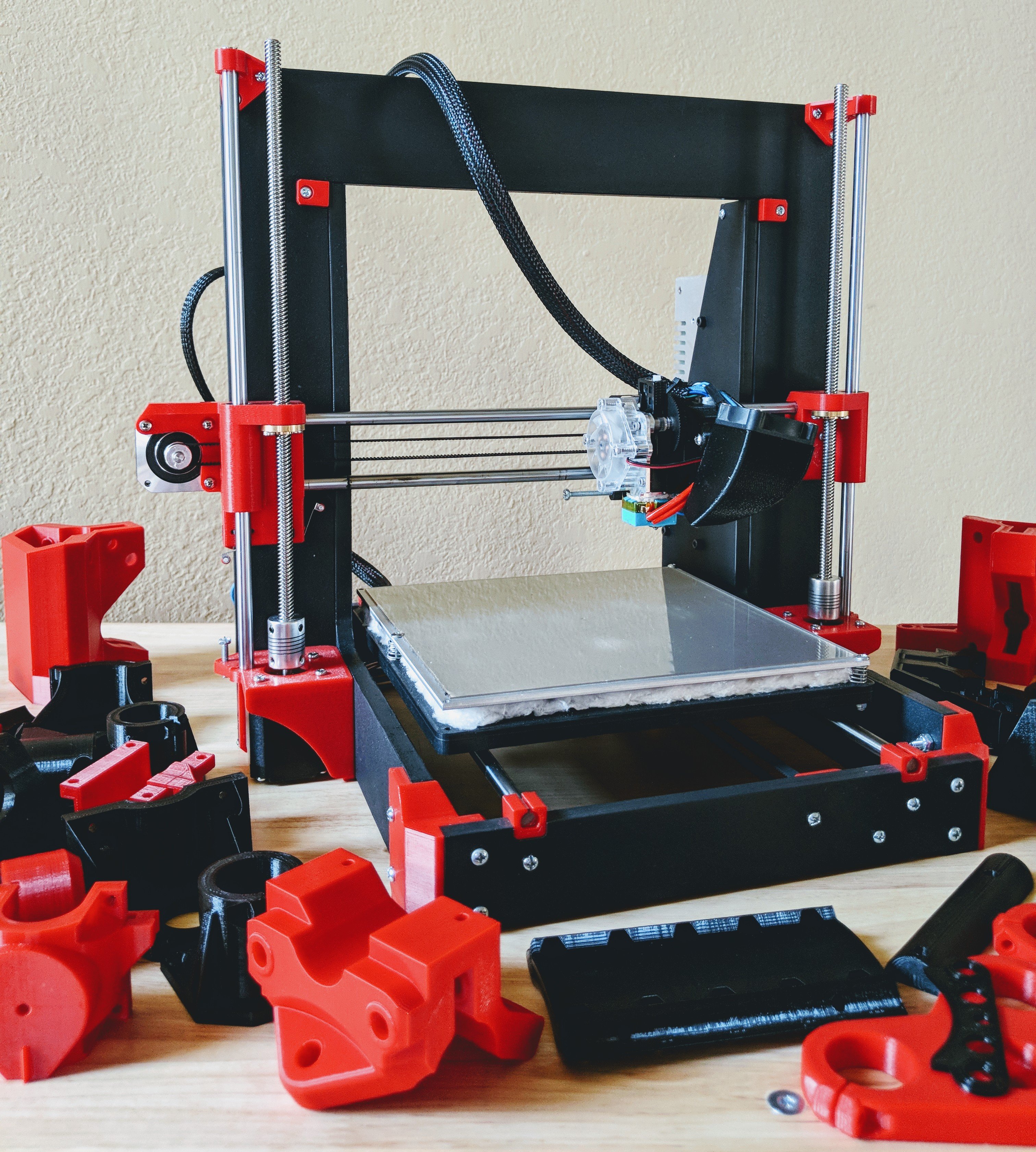
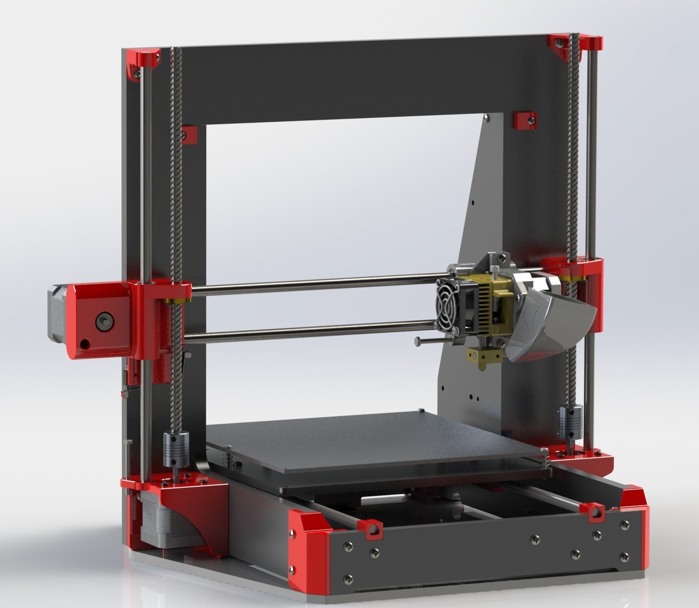
This is my take on a Prusa I3, with a CNC mill friendly frame. This is the MP3DP -V2- Milled/Printed 3D Printer Version 2. This is a fun project to use your new CNC mill for.
The V2 has tightened up some of the designs from my first version, every single part is different. Nothing too major. Better belt placement, better frame geometry, more robust parts, better extruder mount, easier to set home stops, slightly larger build volume, ability to use thicker material for the frame, optional bottom plate for rigidity, better smooth rod handling.
This page
If you just want to open a box and have a ready 3D printer there are a few solid options out there. The MP3DP V2 is a printer for those of you that want to build one, get your hands dirty, and learn a thing or two! Currently this is just a guide, not a full set of instructions. If anything is unclear let us know and we can add a picture or two. Hopefully nothing is to tricky here.
Questions comment – HERE.
Version 1
Version one instructions are here
Flat Parts
The frame components were designed for ⅜″ material this time, the bed support is still good for ¼″ (the lighter the better for the bed). All the parts can safely go above a little thicker than ½″ and as thin as you want for those of you with access to high tech materials. Material thickness will determine some screw lengths as outlined below.
I have included a “Y Speed Plate” for the ultimate bed support. I use insulation under my bed so I also included a full “Y Plate”, also needed for you savages that use 4 corner heated bed mounting. Make sure only to cut the one you need as you do not need both.
All inside corners were designed with ⅛″ diameter or smaller end mills.
Have fun with it, cut in some flavor, no need to have all that material there, you have a CNC machine use it!
Thingiverse hosts the parts Here
| QTY | Part Name | Comments |
|---|---|---|
| 1 | Back mm | |
| 1 | Front mm | |
| 1 | XZ_Frame mm | |
| 2 | Y_Frame mm | |
| 1 | Y-Plate mm | Optional Y-SpeedPlate mm |
| 1 | Optional Bottom | Optional for rigidity. |
Bottom Plate
Completely optional This is the HeffePlate V2, Jeffeb3 made one for the first version. This is just the updated one. If you use it counter sink the screws so it sits flat and it should allow for thinner frame material to be used as well. Overall it just keeps things more square and rigid. The important features are in there so again, get creative this is just a blank flat DXF.
Specialty Parts
Note
Amazon.com links are for illustrative purposes only.
| QTY | Description | Comment | Link |
|---|---|---|---|
| 1 | Control Board | Your choice | Shop – Amazon |
| 1 | Extruder | Your choice | Shop – Amazon |
| 1 | Power Supply | >20A | Shop – Amazon |
| 4 | Steppers Nema17 | >40 OZ/IN | Shop – Amazon |
| 1 | Heated Bed | Optional Recommended | Shop – Amazon |
| 2 | X 8x370mm Smooth Rod | Shop – Amazon | |
| 2 | Y 8x350mm Smooth Rod | Shop – Amazon | |
| 2 | Z 8x320mm Smooth Rod | Shop – Amazon | |
| 11 | LM8UU | Shop – Amazon | |
| 2 | T8 Leadscrew 300mm | Recommended Lube | Shop – Amazon |
| 2 | T8 Nut | Shop – Amazon | |
| 2 | Coupler 5mm to 8mm | Shop – Amazon | |
| 2 | GT2 16T | Or other w/ Firmware edit | Shop – Amazon |
| 2 | GT2 16t Toothed Idler | Or match pulley | Shop – Amazon |
| 3 | Limit Switch / EndStop | Shop – Amazon | |
| 1 | Print Fan | Shop – Amazon | |
| 3 | Bed Springs | Shop – Amazon | |
| 1.5M | Belt GT2 | Shop – Amazon |
As an Amazon Associate I earn from qualifying purchases.
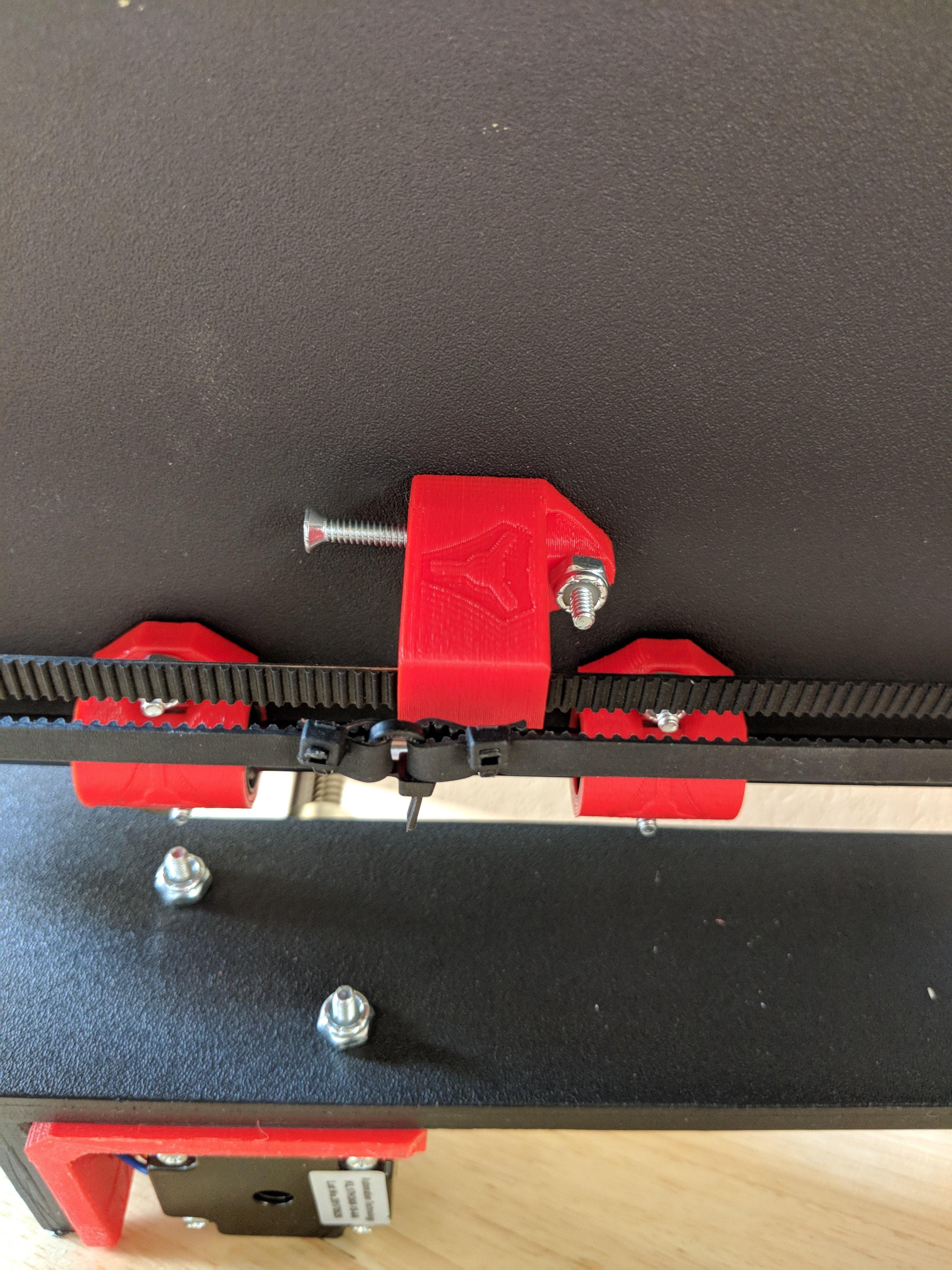
Belts
I love me some cable ties…
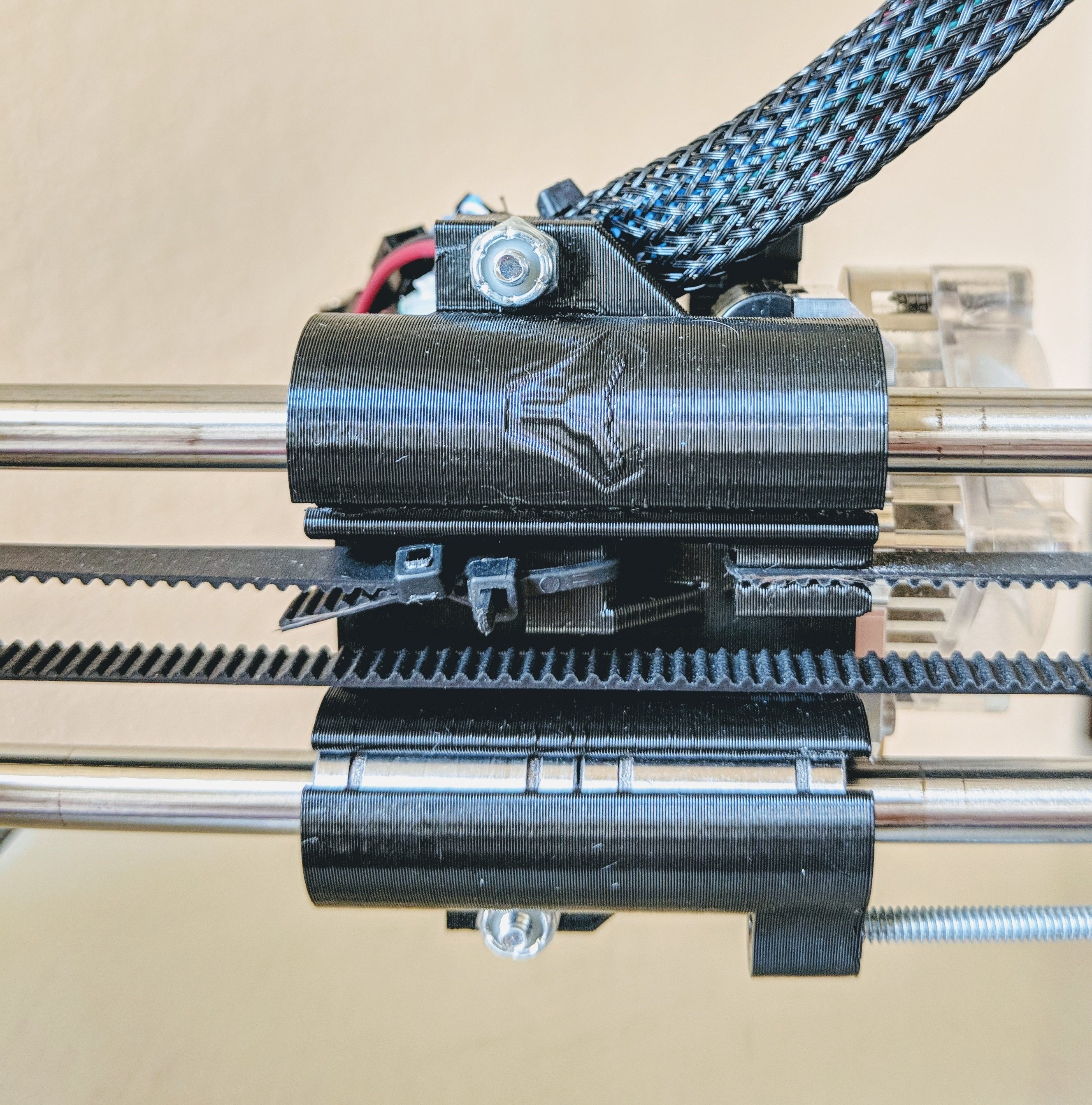
For the bed I tried something new, and I like it. Pass through the block and tension the other parts. Make sure the ends clear and do not hit the pulley or idler. Better alignment?
GT2 Idlers
I took a while to release these parts because my idlers kept seizing up. I have two suggestions, first lube them well, I am using the super lube from the shop, no issues since. Second belt tension does not have to be superhuman here. Start loose and only tighten the belts if you notice issues. Too tight=excessive ringing and premature idler damage, Too loose=soft rounded corners and poor wall consistency.
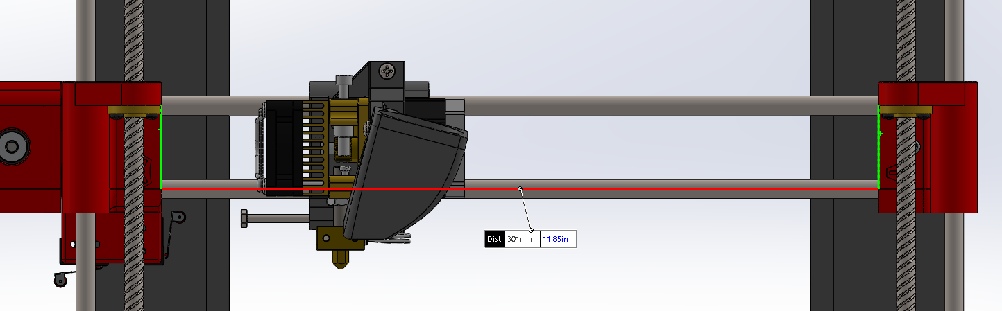
X Axis
Easy adjust, more consistent belt tension. Use the screws to set the smooth rods into place, or use super glue like before.
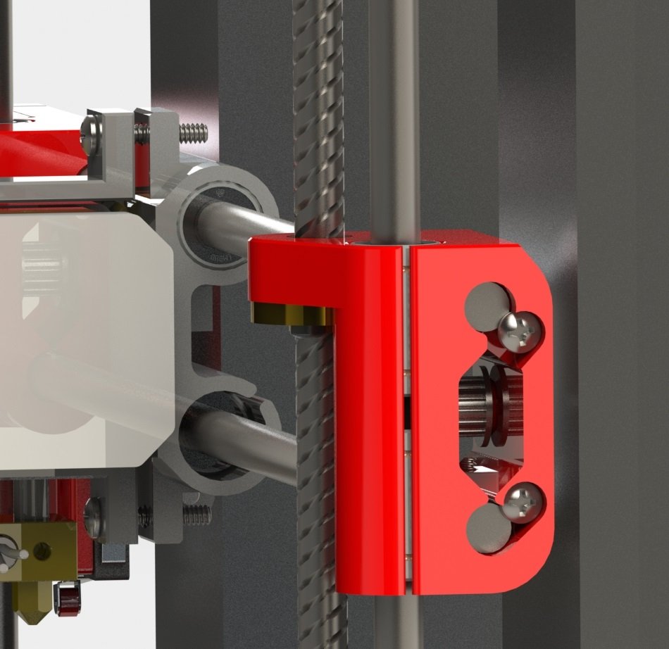
They should be adjusted top and bottom, to 301mm. you can measure this top and bottom to ensure the ends are parallel.
Wires
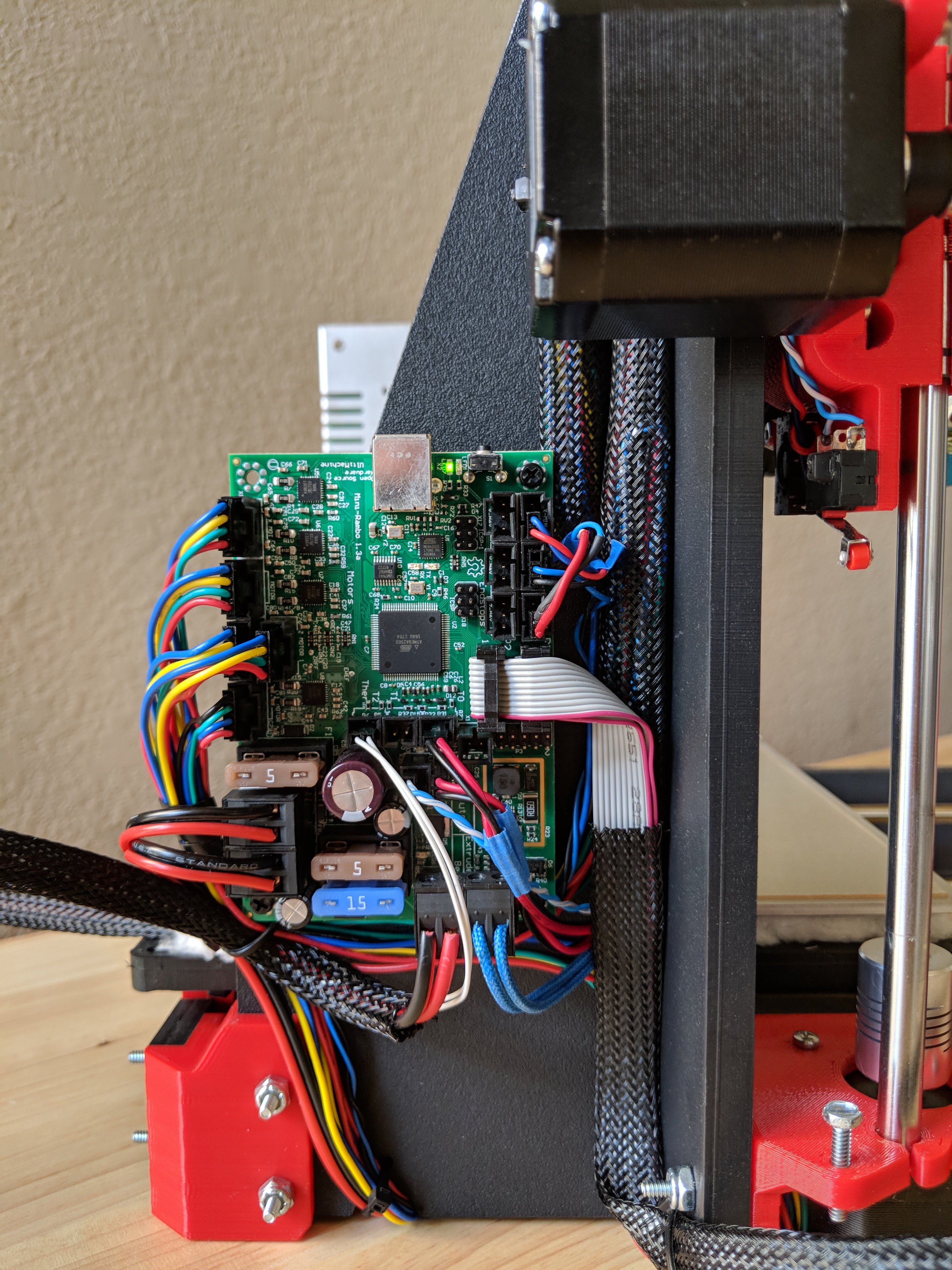
If you need a good first printing project how about a box to hide those wires, Gnarly Mini-Rambo Case, or a case for the LCD?
Extruders
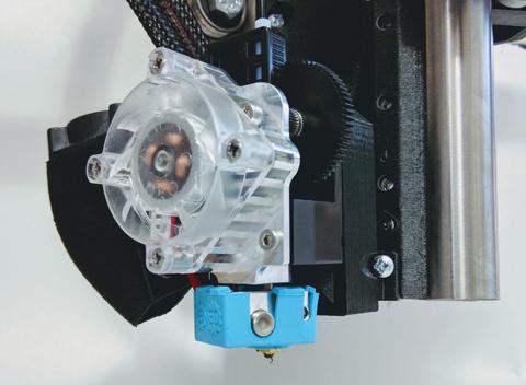
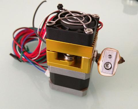
I have designed this with both the Titan Aero , and the MK8 in mind they both work great choice is yours. The mounting plate is pretty straight forward the holes are easy enough to utilize for anything you might need if you don’t like either of those. The holes are 64mm apart.
Printed Parts
Infill on the parts is not a big deal I use 15%-20%, but make sure to use 2-3 perimeter walls to keep the through hole support.
Thingiverse hosts the parts Here
| QTY | Name | Time hours:mins |
|---|---|---|
| 2 | Brace | * 7:25 |
| 2 | CornerL | * |
| 2 | CornerR | * |
| 1 | extruder strap V2 | * |
| 1 | MK_Fan | * |
| 1 | Upper_L | * |
| 1 | Upper_R | * |
| 1 | X | * |
| 1 | XZ_Motor | # 3:55 |
| 1 | XZ-End | # |
| 3 | Y Bed Bearing Blocks | * 3:11 |
| 1 | Y_BlockV2 | * |
| 1 | Y_Mount | * |
| 1 | Y-Bearing | * |
| 4 | YClip | * |
| 1 | Z_Mount_L | # 4:50 |
| 1 | Z_Mount_R | # |
| 1 | Optional X Cap | # |
| Total | 19:21 |
*, #, designates the groups I print them in and total print time for that group.
Hardware
Here is a simplified hardware list, a few parts are made for shorter hardware, but this is as simple as it gets. You can also go longer on most all of these. M3.5mm is almost a direct fit for the #6-32 screws, some seem not to want to order these online if they can’t find them locally so an M4 will probably work. I really suggest just ordering a box of M3.5’s for simplicity.
| Qty | Name | Comment |
|---|---|---|
| 3 | #6-32 x 1.5″ | Hex heads. These are for the XYZ endstop adjustments. |
| 60 | #6-32 x ??(1″) | Frame screw length depends on frame material thickness, round up in length. See Below. |
| 55 | #6-32 Nylocs | |
| 20 | M3 x 10mm | Stepper and T8 nut screws |
| 5 | M3 x 22mm | Bed adjustment and Idler screws |
| 4 | M3 Nylocs | |
| 3 | Control Board screws | mount screws,standoffs dependent on your board. e.g. (M3x22mm with 10mm rubber standoffs) |
| 3 | Power supply screws | mount screws,standoffs dependent on your power supply. e.g.(M5 x 20mm 7mm rubber standoffs) |
The control board and power supply screws will depend on your hardware, frame thickness and preferred standoff distance, easy thing to do is cut rubber hose as the standoffs.
Screw length
This is the hard part. A ¾″ screw is a thread or two away from fitting a ⅜″ frame board, counter sinking would make them fit. I chose to use 1″ instead. you need .423″ (that is the printed part and nut thickness) plus the thickness of your frame / bed material, minimum. Longer should not be an issue.
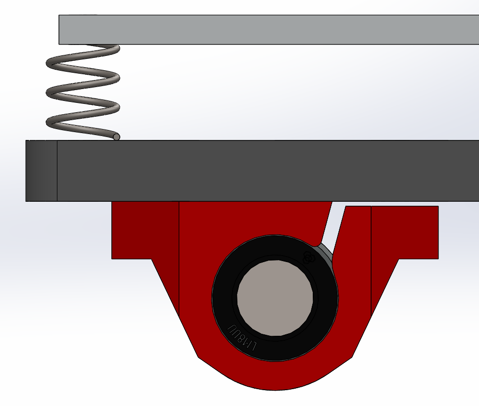
Bed bearings
Trying out a new style here, one side is shorter to allow for clamping if necessary. I found it usually is not, If you over tighten it you can actually crush the bearings and damage them. Default to super loose or no clamp screw/nut at all. Just a screw on the flush side should be enough.
EndStops
The endstops should be wired Normally Closed, NC, for safety.
Initial leveling
- Rough
- When setting up your printer first level your X axis. Measure from the top of the motor mounts to the bottom of the vertical bearing blocks. The next thing is to level the bed. This is done by setting the 2 screws on the right side (front and back) to the nozzle height, then set the single screw on the left of the bed.
- Home
- Set each of the three endstop trigger screws such that the nozzle comes to rest just touching the print surface in the nearest left corner.
- Final and tune up
- Heat up the system, make sure the X axis is still level with the motor mounts, make sure the bed is still level with the nozzle. Adjust Z home trigger screw to get the correct first layer.
Firmware
The beta Marlin 2.0 version is on the GitHub page , or the old MP3DP firmware works (found below as a backup). There are nots on the GitHub version there are two settings that need to be changed for the MK8 or the Titan Aero, the thermistor value 11 for the MK8 or 5 for the Aero, and 100 steps for the E on the MK8.
Slicer and MK8
If you need some initial settings to get started there are slicer settings at the end of this page , and a breakdown of an MK8 assembly.