Low Rider CNC 2
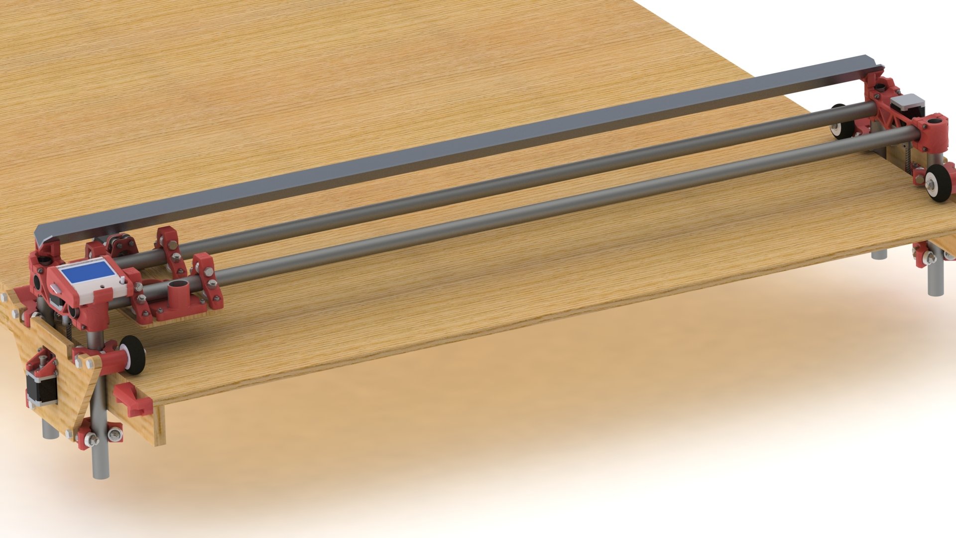
The LowRider2 CNC is my revised version of a CNC router that can handle full sheet material! Of course you can go smaller. If the MPCNC is not big enough for you this picks up where that left off.
- Thingiverse Printed parts files:
- 25.4mm version
- Thingiverse Link
- 25mm version
- Thingiverse Link
- Hardware list
- Link
This CNC router can handle any length (within reason), the Y direction is only bound by your table length.
Width (X direction on rails) should always be the shorter axis and is recommended to keep the work area no larger than 4′ on this axis.
The Z direction (height) is best kept to a 3-4″ maximum for wood, with that being said, you can make the usable z length as much as you want you will be working from the bottom up, so go to town.
Calculator for table, rail, and belt lengths.
Version 1
Version one instructions are here
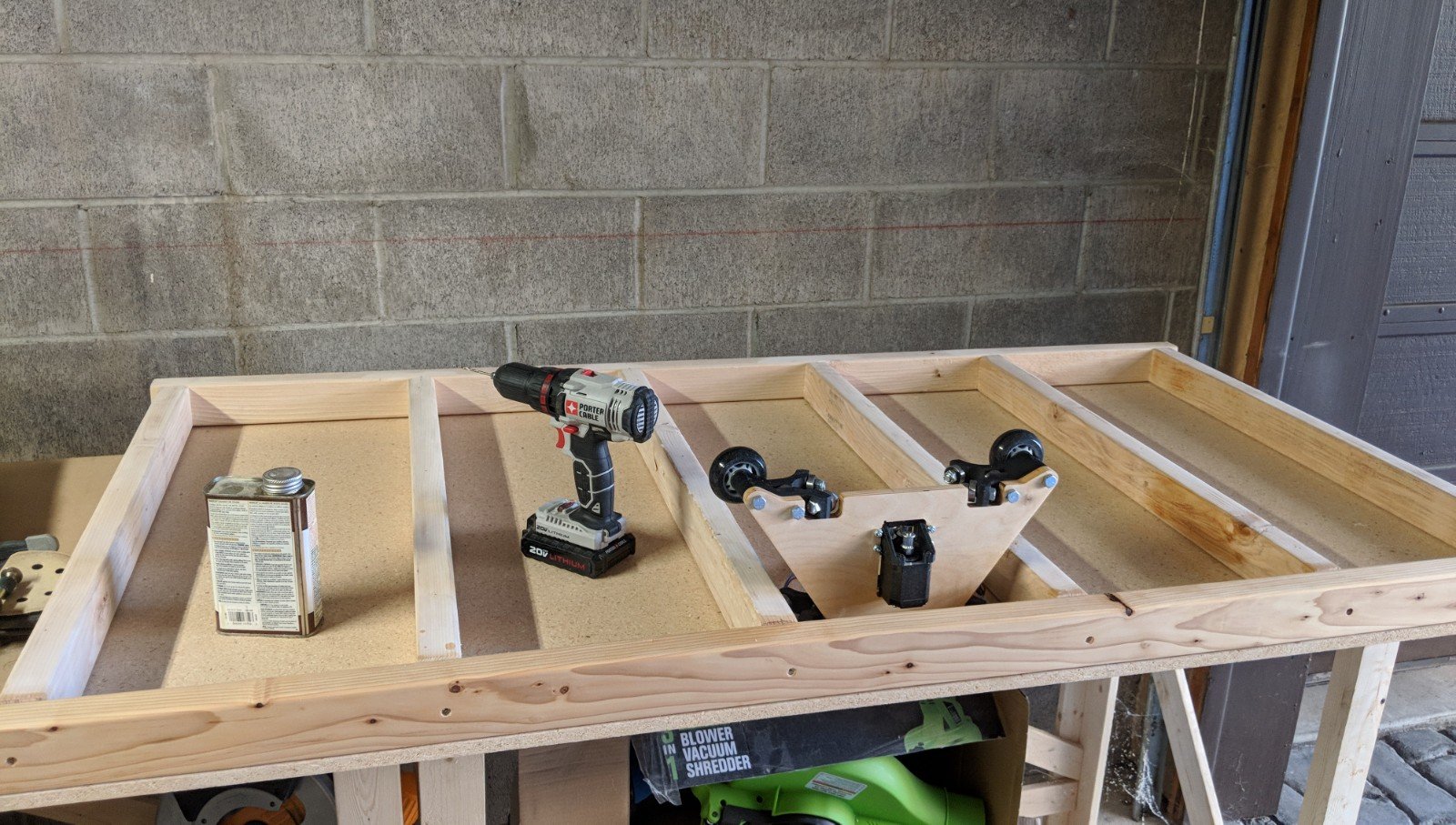
Assembly
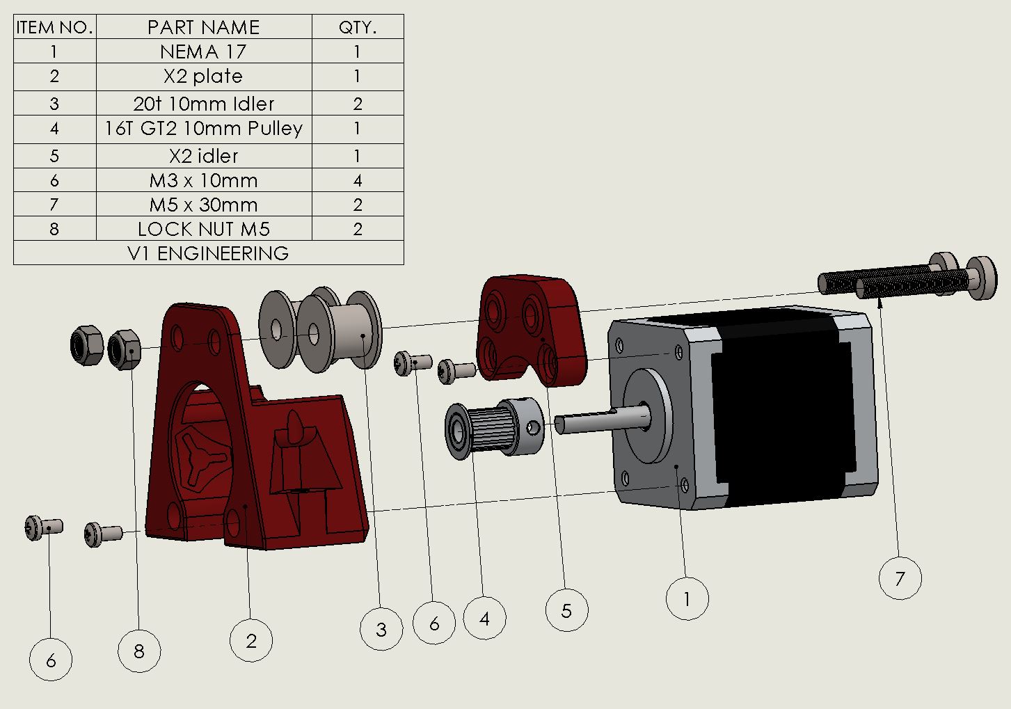
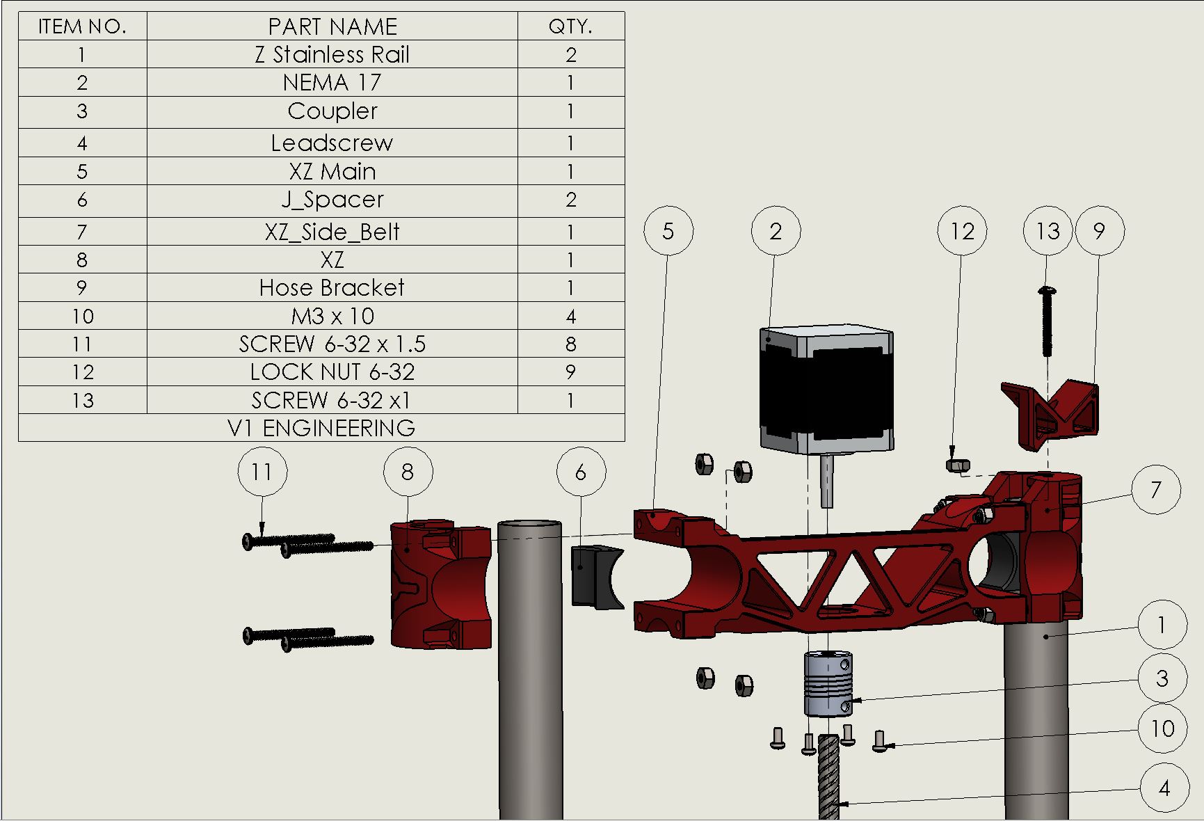
All quantities shown in the drawings are for each assembly, not total quantities.
Center Assembly
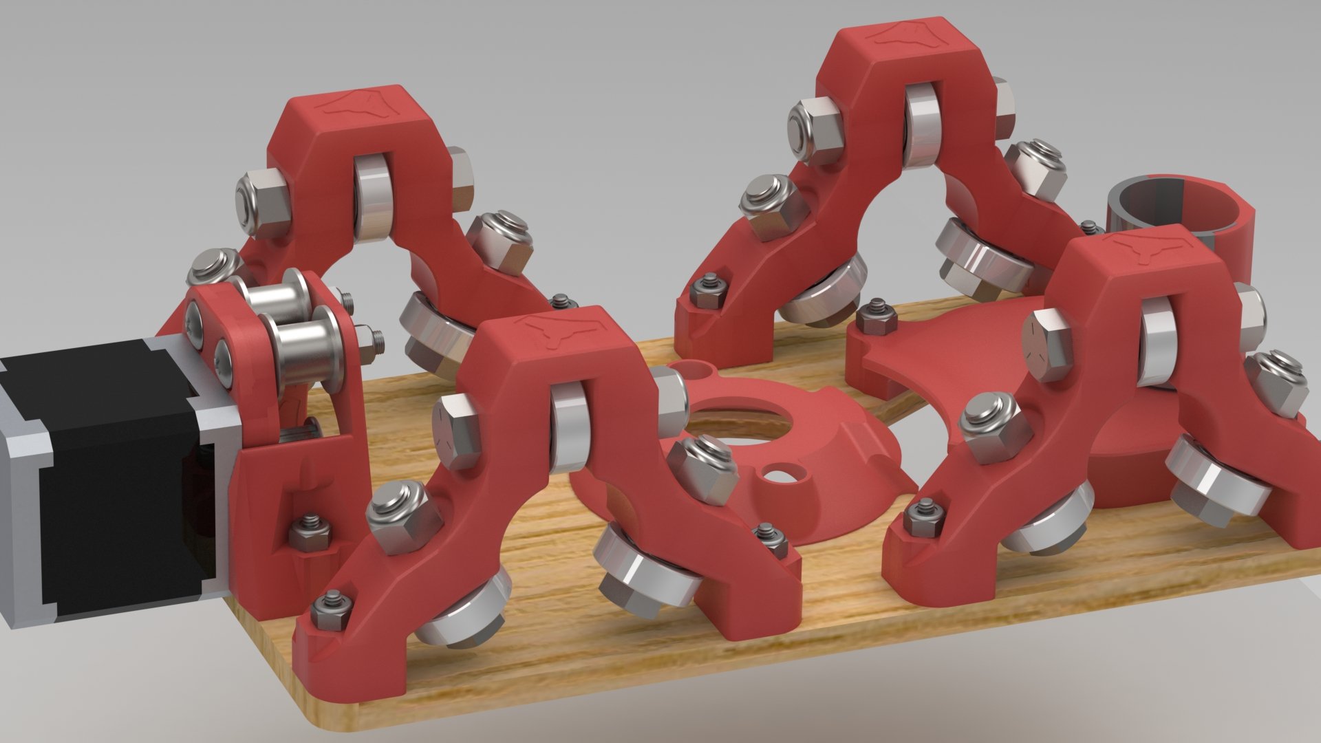
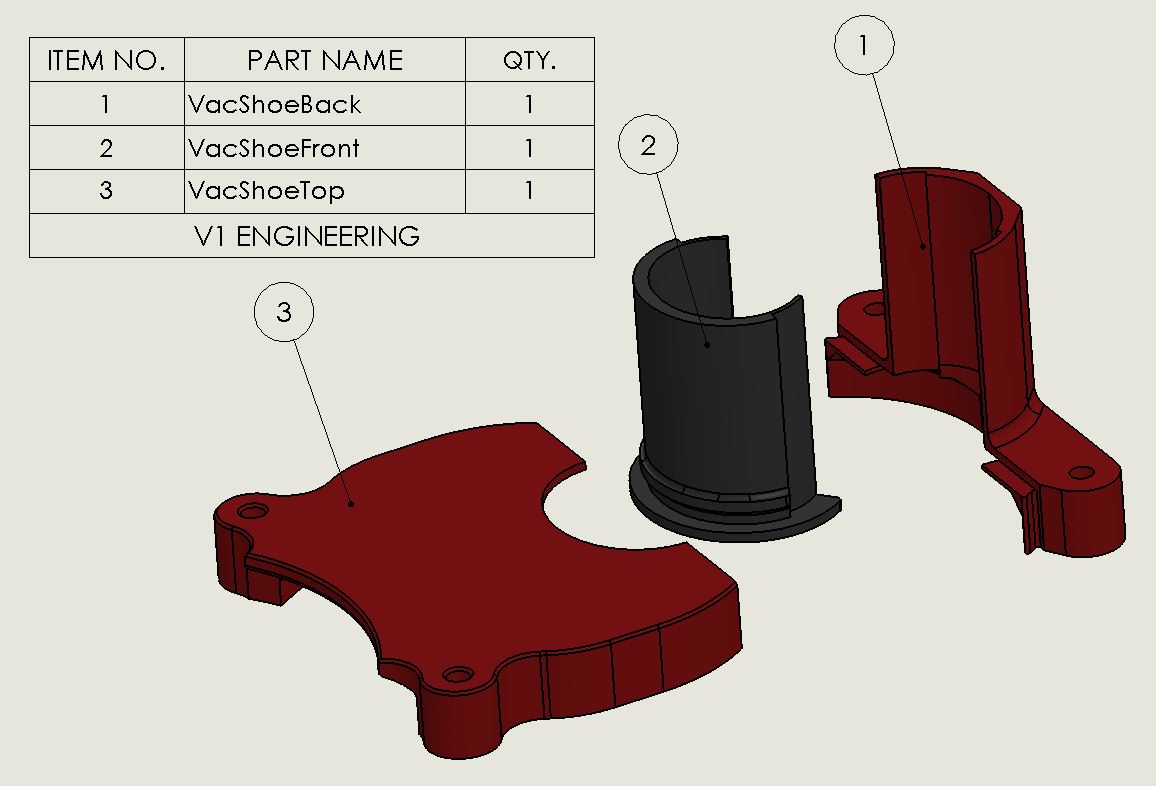

The VacDuct, sits inside the router clamp body to separate the router exhaust and the vacuum intake.
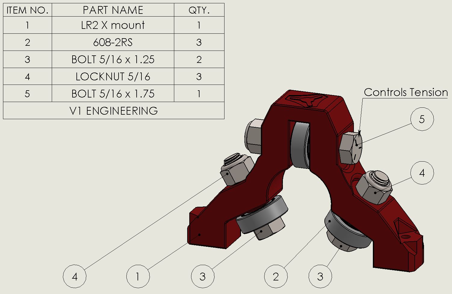
When setting the tension for the X Mounts after attaching them to the plate set the tension for each mount individually. An easy way is to use the Z rail and run it through each one, very light tension, you might not even need to add any, the mounts are interference fit.
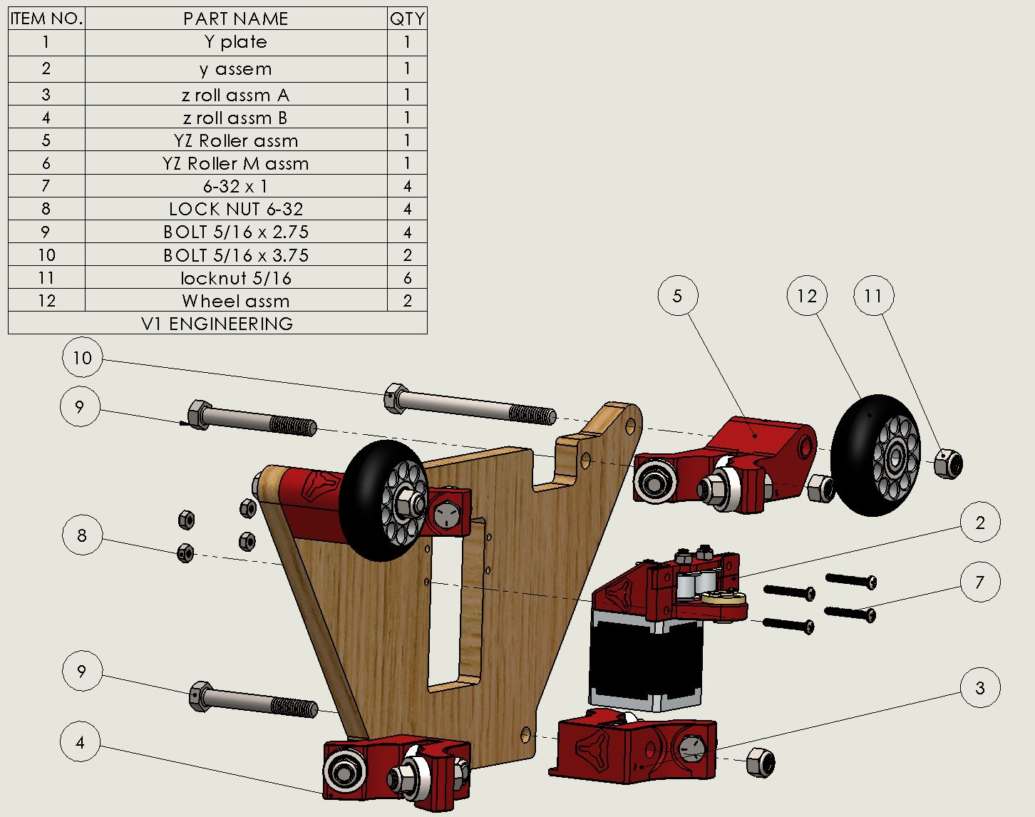
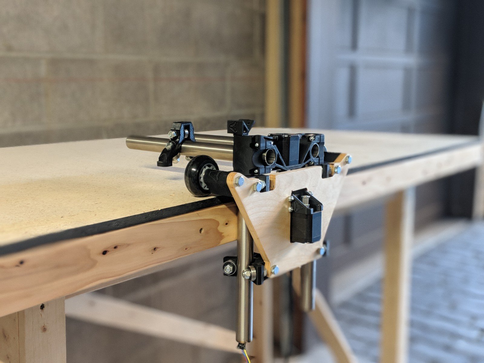
Z Assemblies
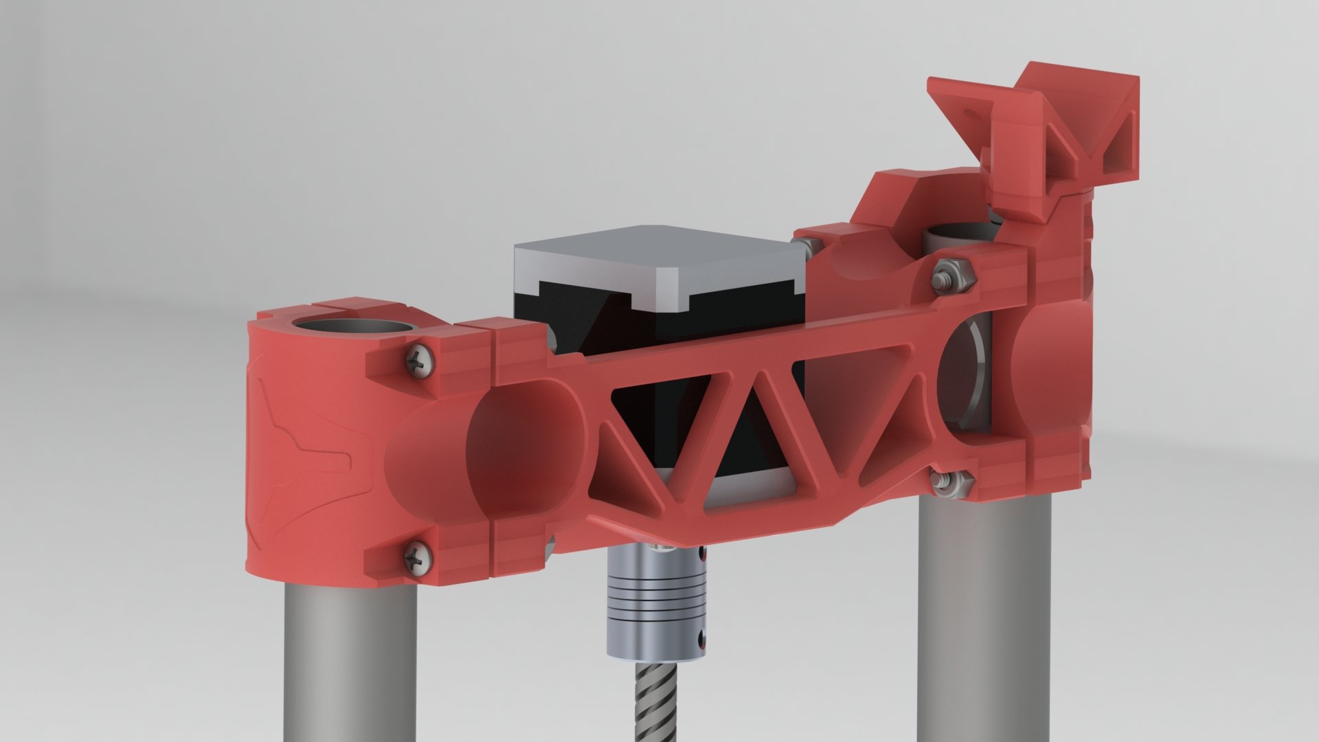
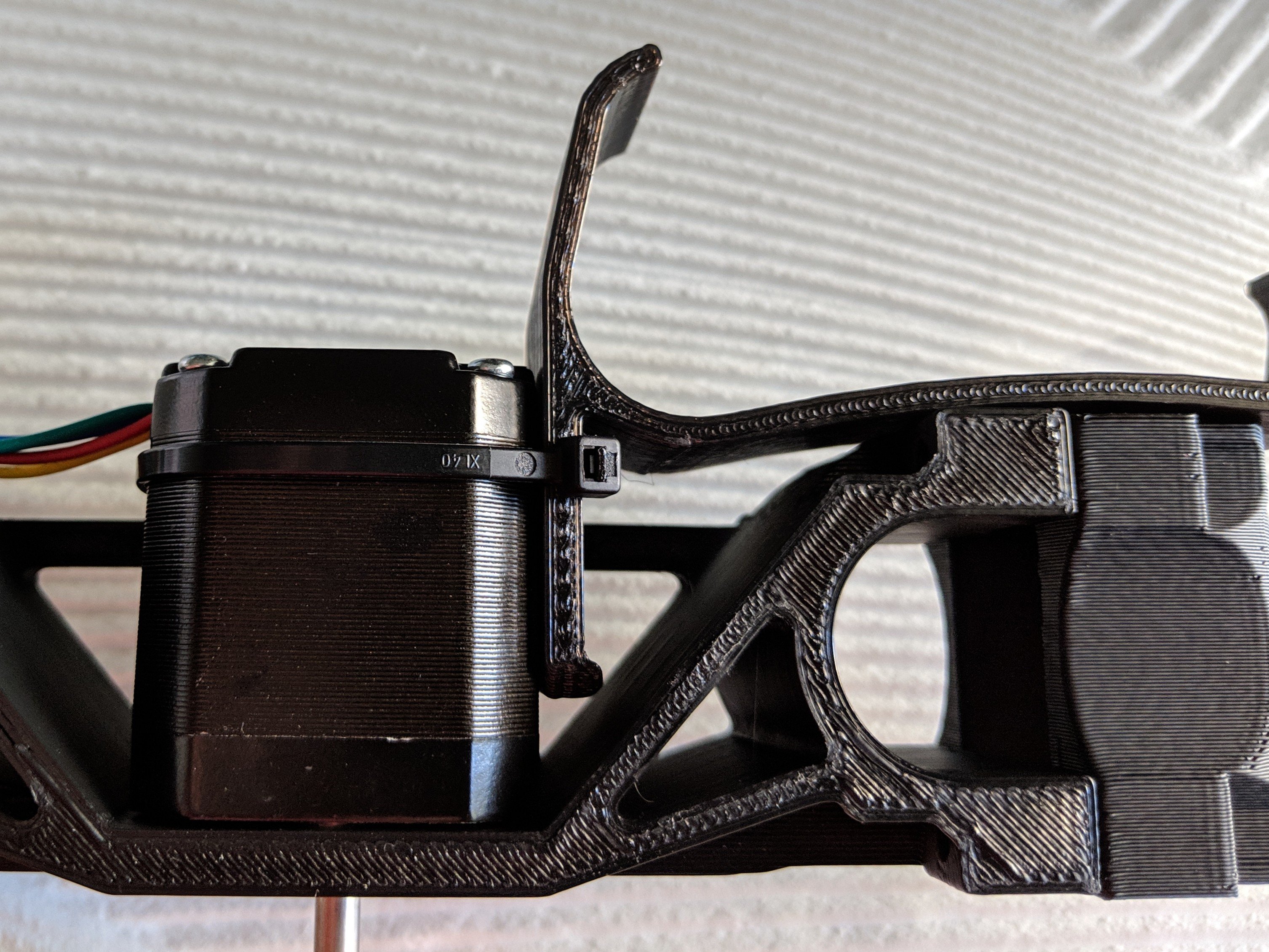
- Check for correct orientation of XZ Main and XZ.
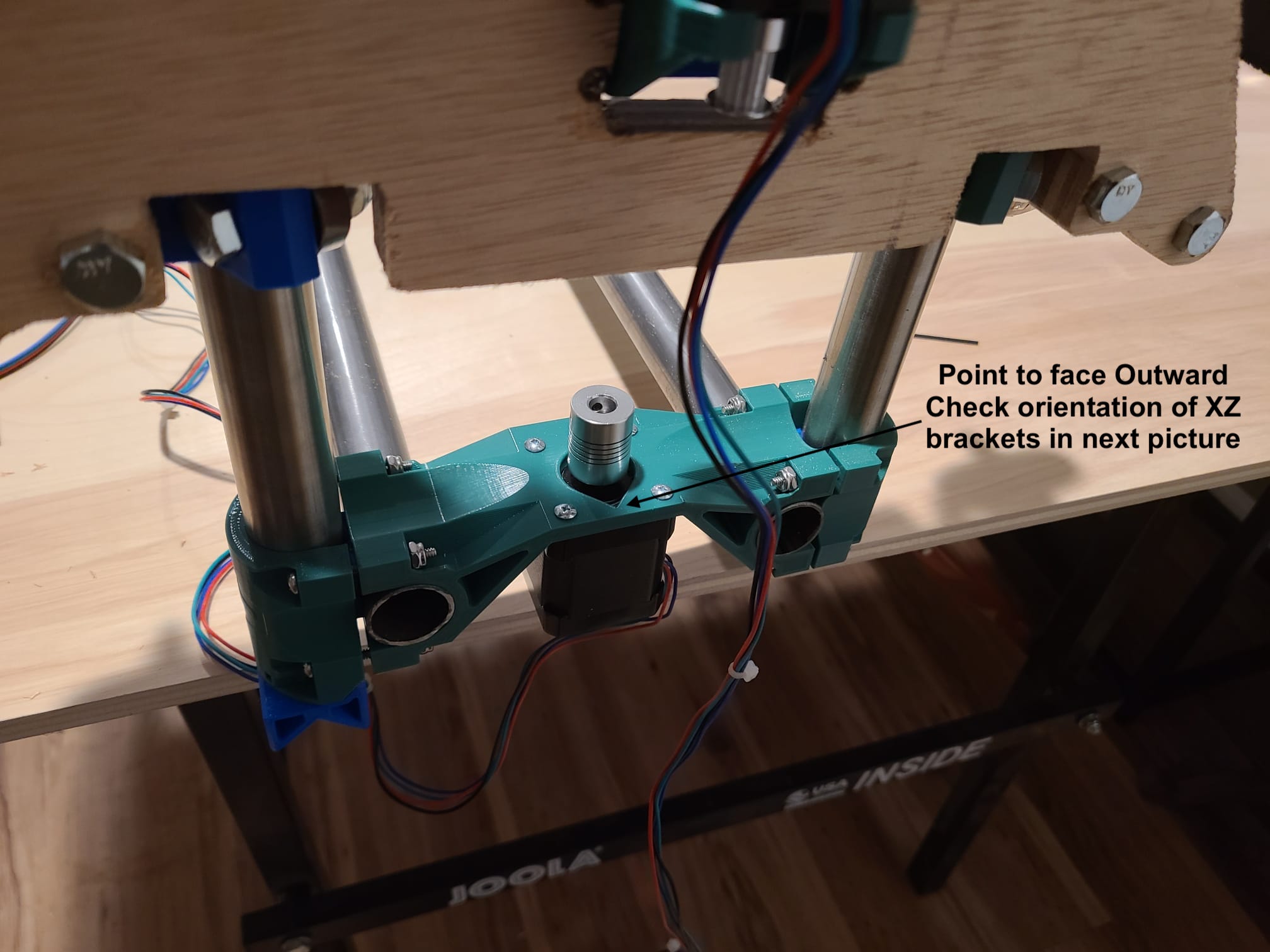
Stepper mounting hole in XZ Main, pointy side should face outward (facing away from the table).
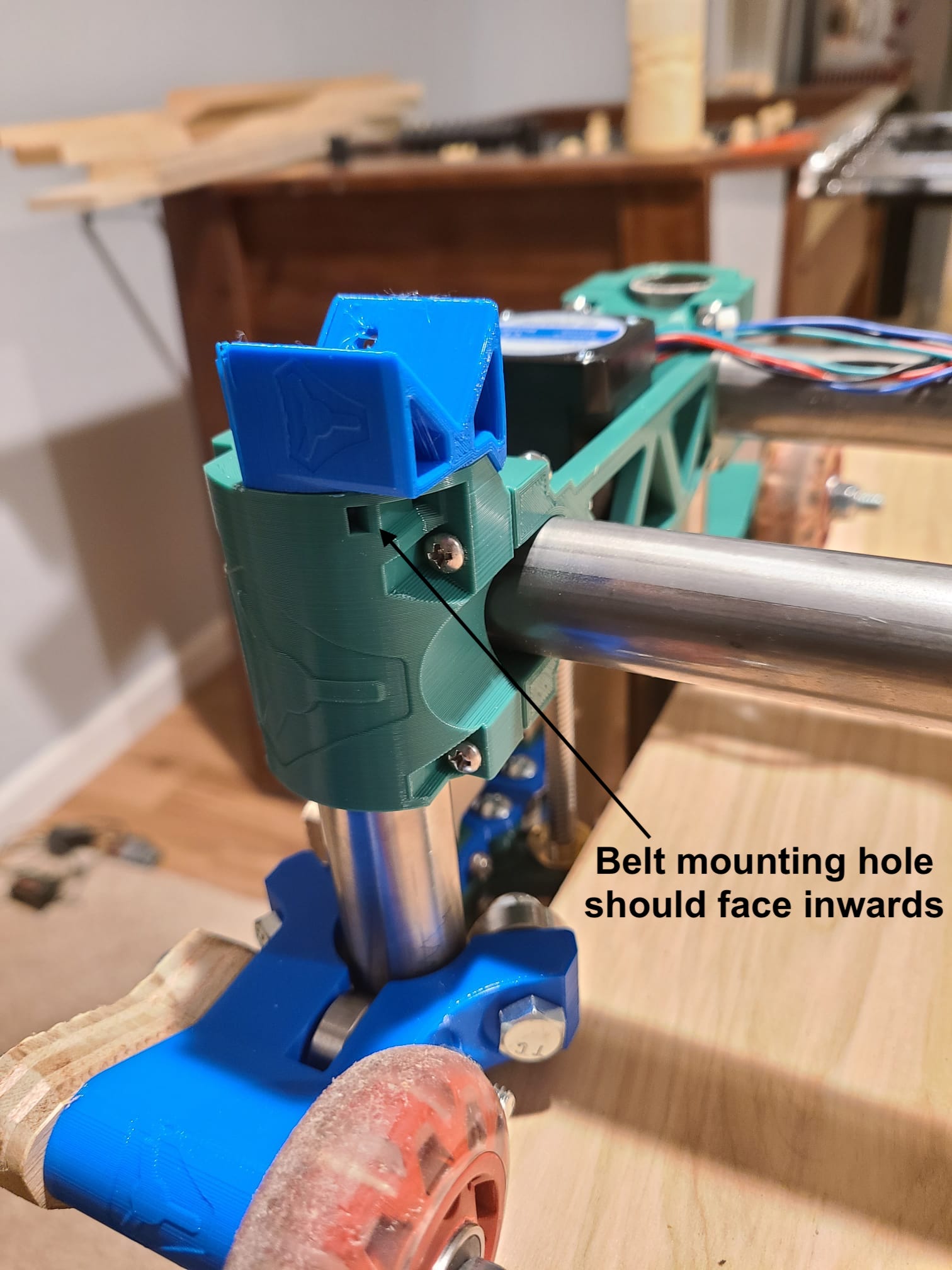
Belt mounting hole on XZ should face inward (Facing the table).See pictures for details.
When fully assembled the XZ main’s should sit completely flat on the YZ rollers. If not check these three points.
- Double check that the Z rails are parallel, same distance apart at the bottom as they are on the top.
- If you loosen the corner brackets up too much and the XZ mains still won’t sit flat the larger bolts are not tensioned properly / evenly (probably way way too much).
- Make sure all four notches are above the end of the Z rails.
The XZ & XZ_side should be installed with an equal gap on all four screws. There should be a gap of a few millimeters equally on each side of the corners to the XZ Main. These parts can alter the Z rail angles so care is needed. They do not need to be extremely tight; a little pressure goes a long way.
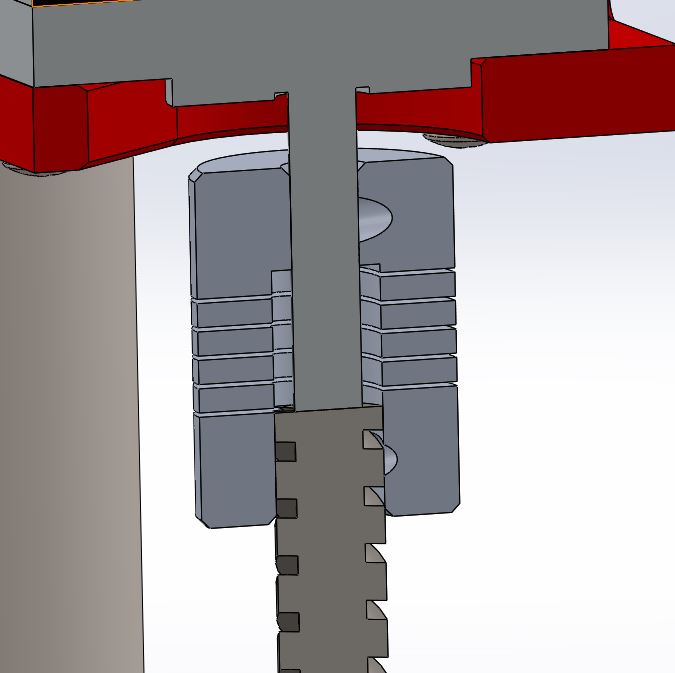
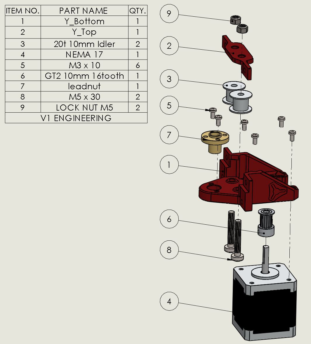
This is how these couplers should be used. The coupler should not be compressed, if anything a little stretch to make sure the lead screw is in contact with the stepper shaft. This prevents bouncing. The lead screw should be only inserted as far as the coupler bottom collar. This lets the stepper shaft and lead screw to move for any minor misalignment.
Seat the grub screws on the shaft trying to get the straightest connection possible. If you hit an edge it will get wonky just give it a little turn and try again. On the stepper shaft tighten the flat screw first then the one that hits the round surface.
Do not forget to lube the Z lead screws.
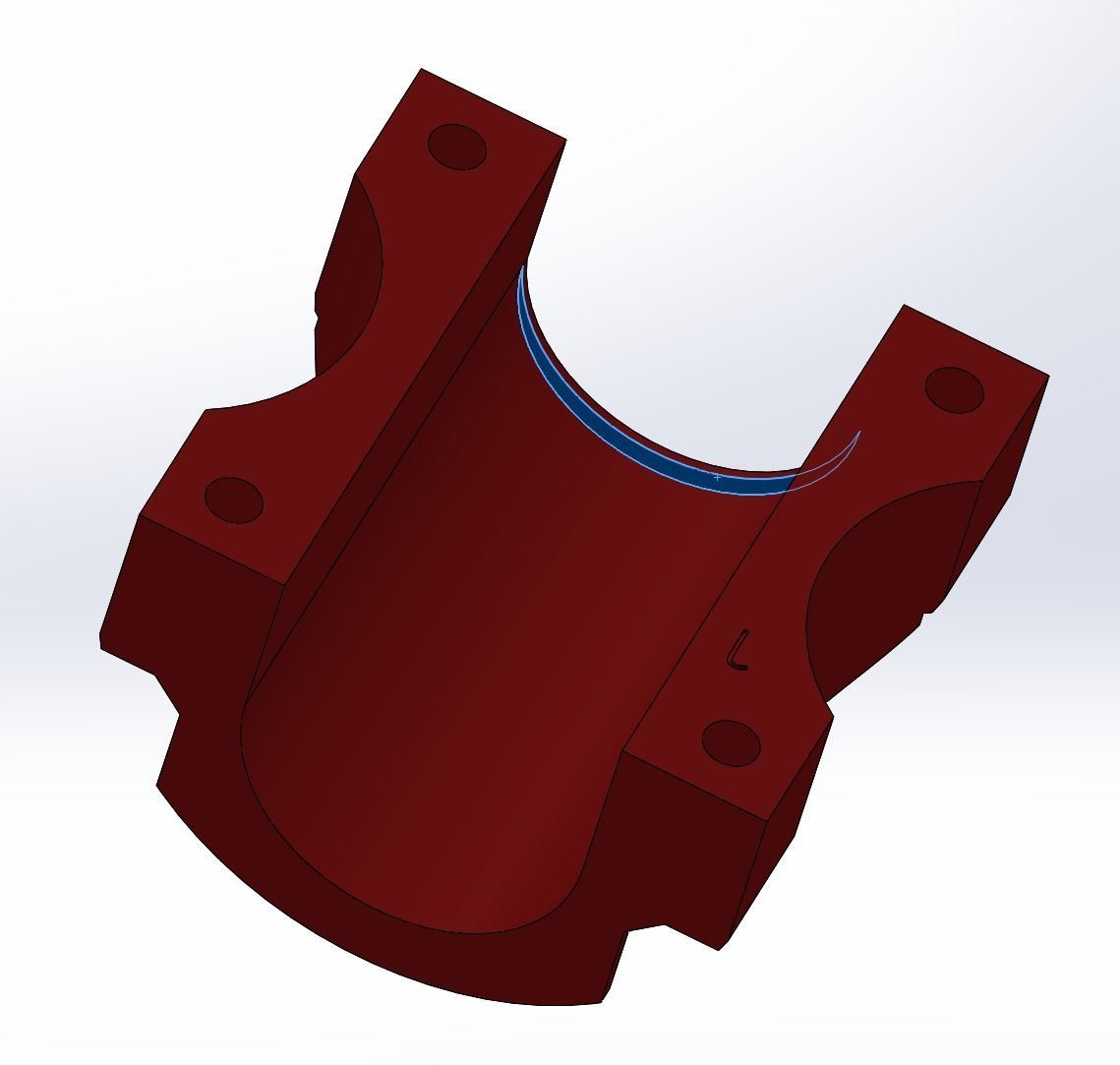
There is a small notch / ridge to prevent the Z rails from coming out of the top on all 4 parts. If your rails are crooked this is where to check.
Sides

It is best not to tighten the M3 screws all the way on the T8 nuts. This allows for a touch of misalignment and smoother Z action. Don’t worry, their only job is to stop rotation and gravity does the rest.
Belts
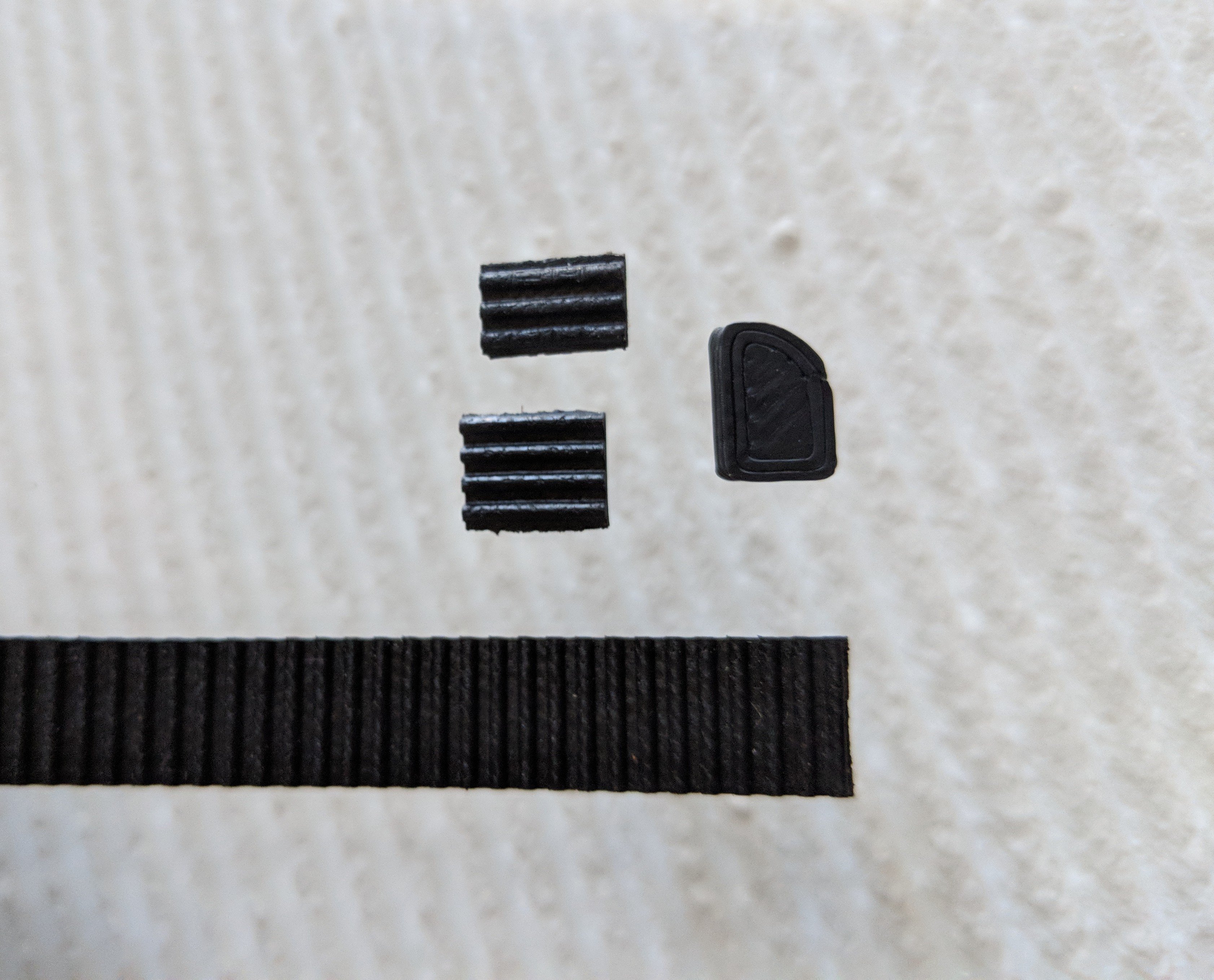
Belt Insert
Why?
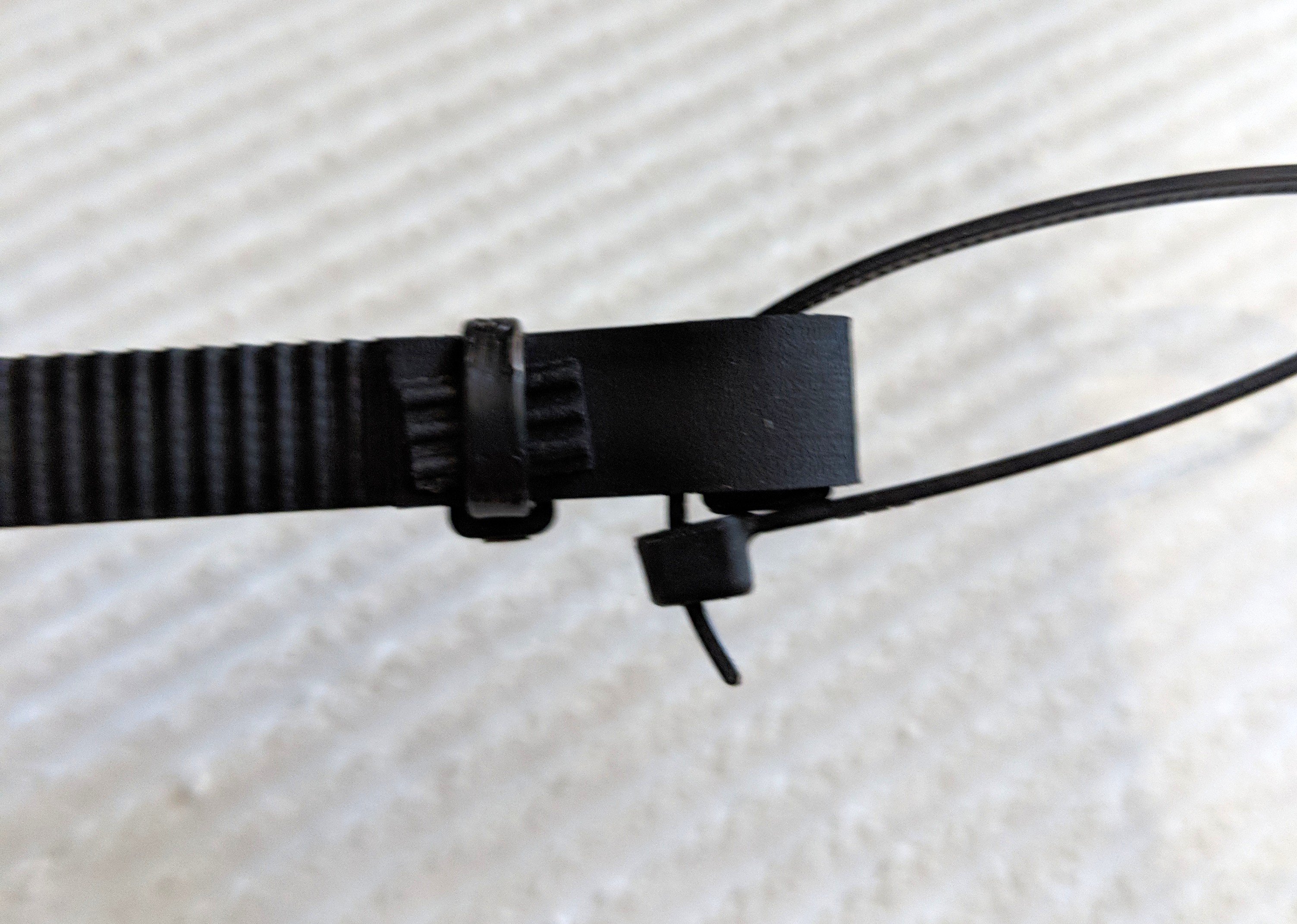
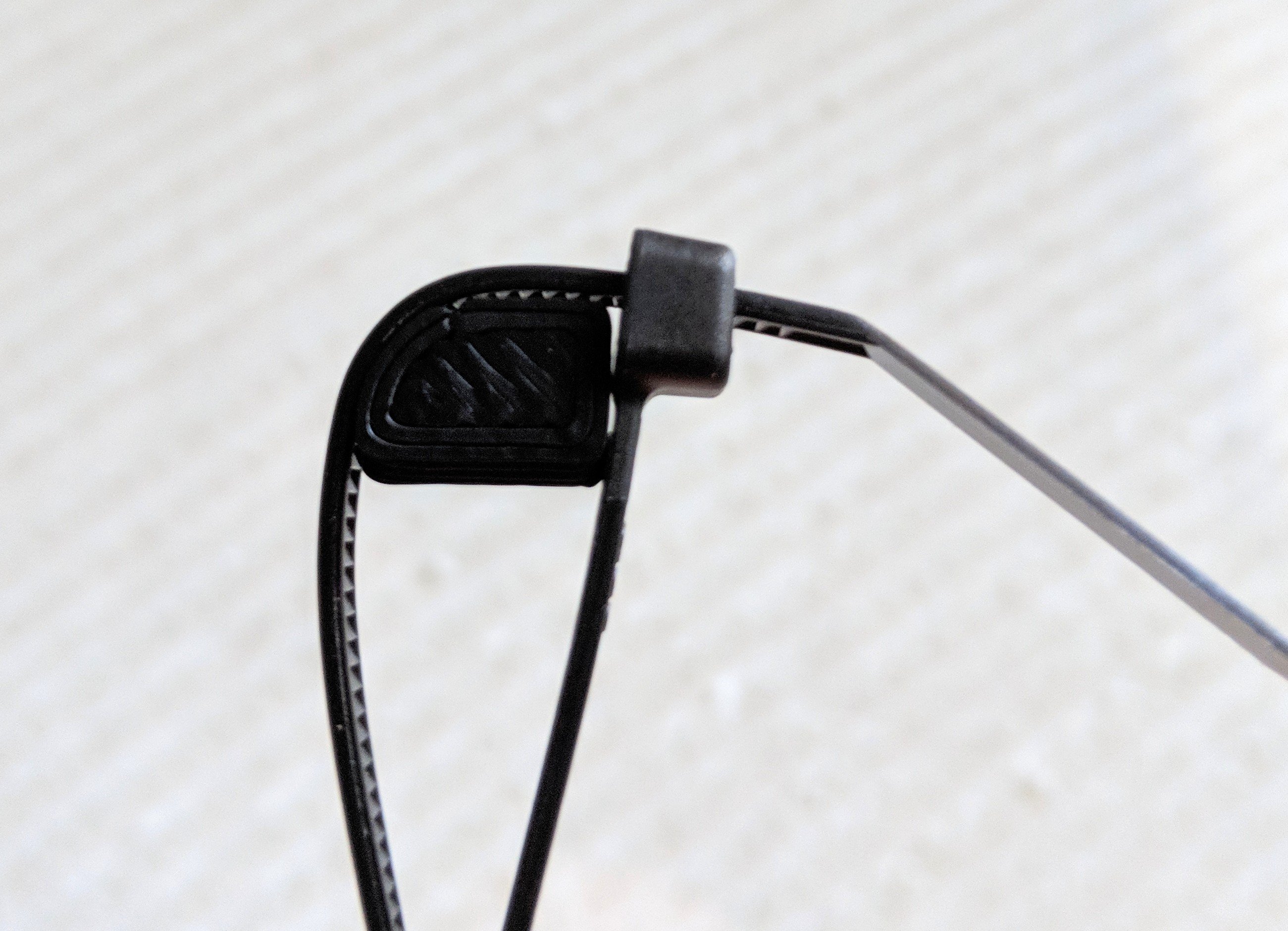
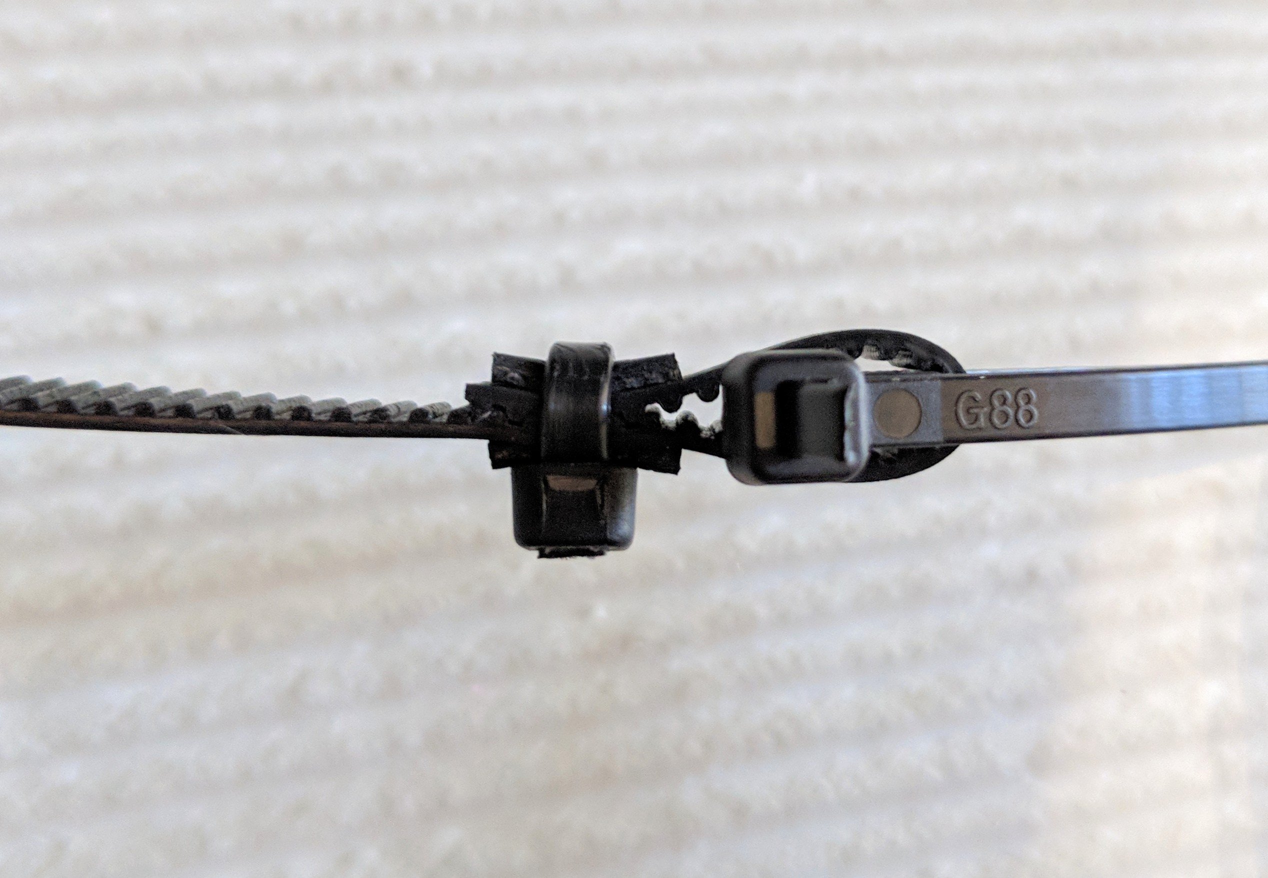
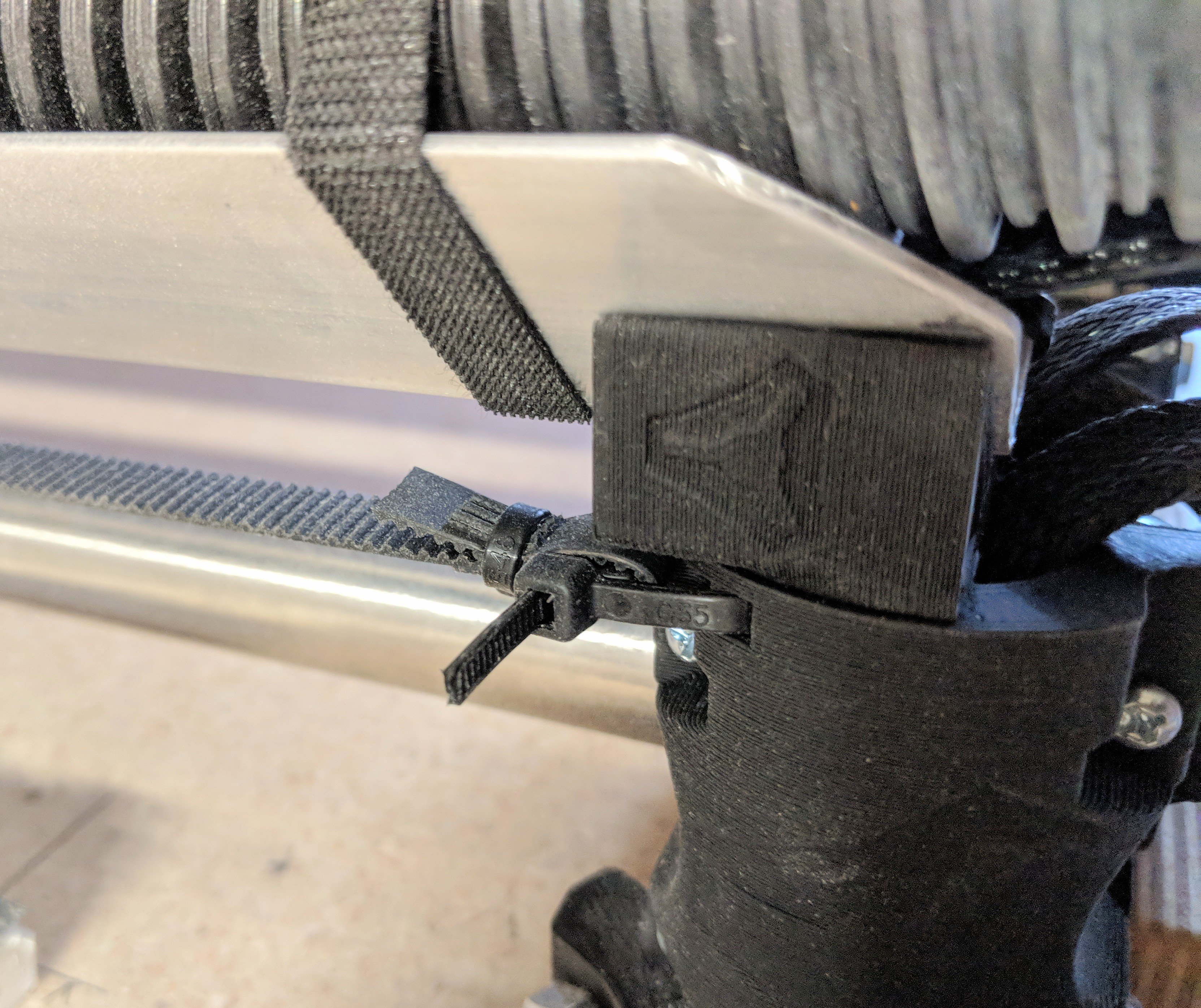
The cable_tie_insert was made to eliminate the flex and bounce of the cable tie and belt connection. This will help keep a reasonable arc in the cable tie at the belt end provided you use the clasp end as shown and the belt flat. This should eliminate cable tie/belt flex on a properly tensioned belt and the tension should stay true longer.
The other end of the cable tie connection is rounded internally on all printed parts with a similar arc.
Using a few segments of the belt itself when securing the end ensures a better connection on the belts teeth. 3-4 teeth facing teeth up will make for a rounder surface of the cable tie that secures the folded belt. This will prevent a wide belt from cupping and slipping teeth.

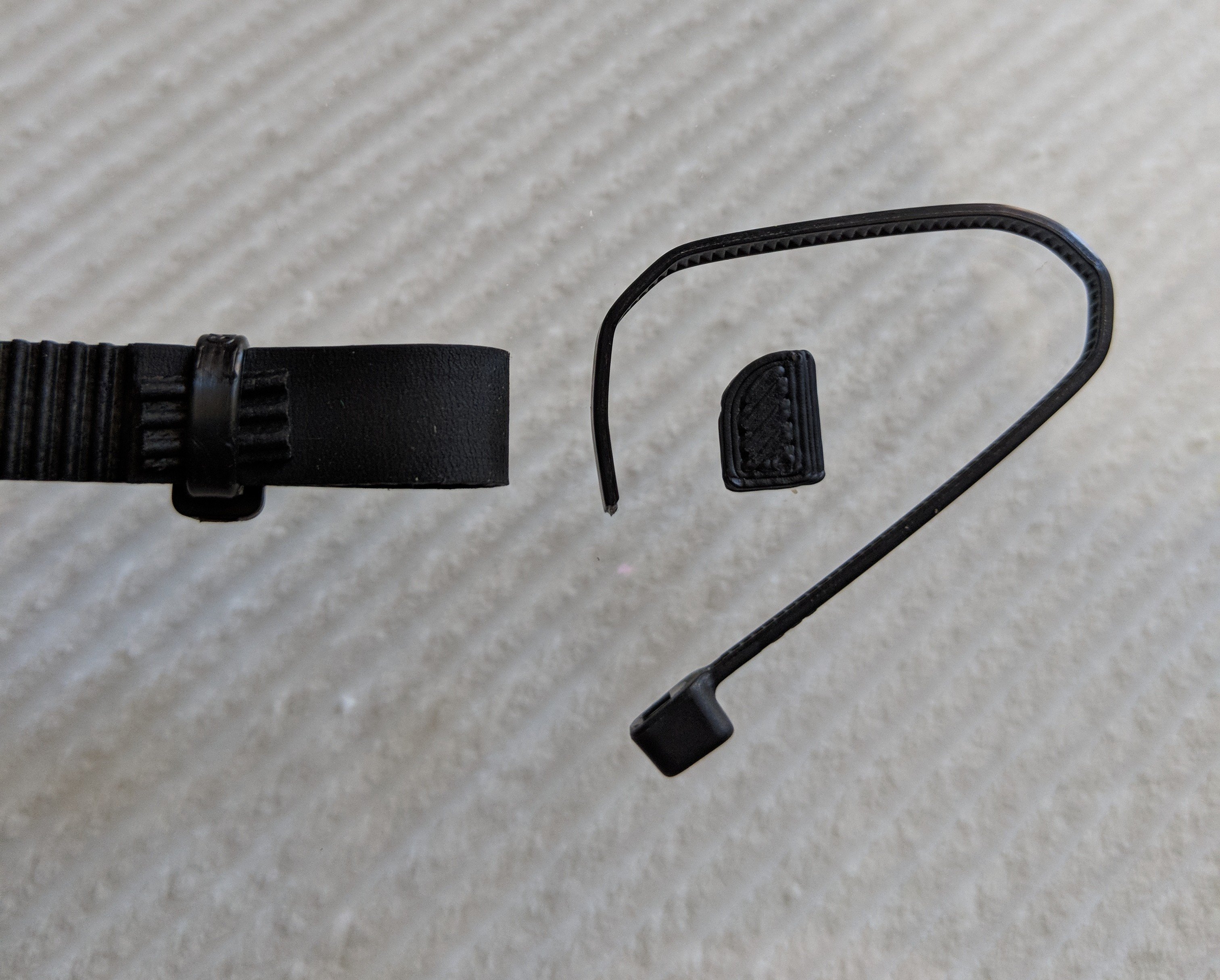
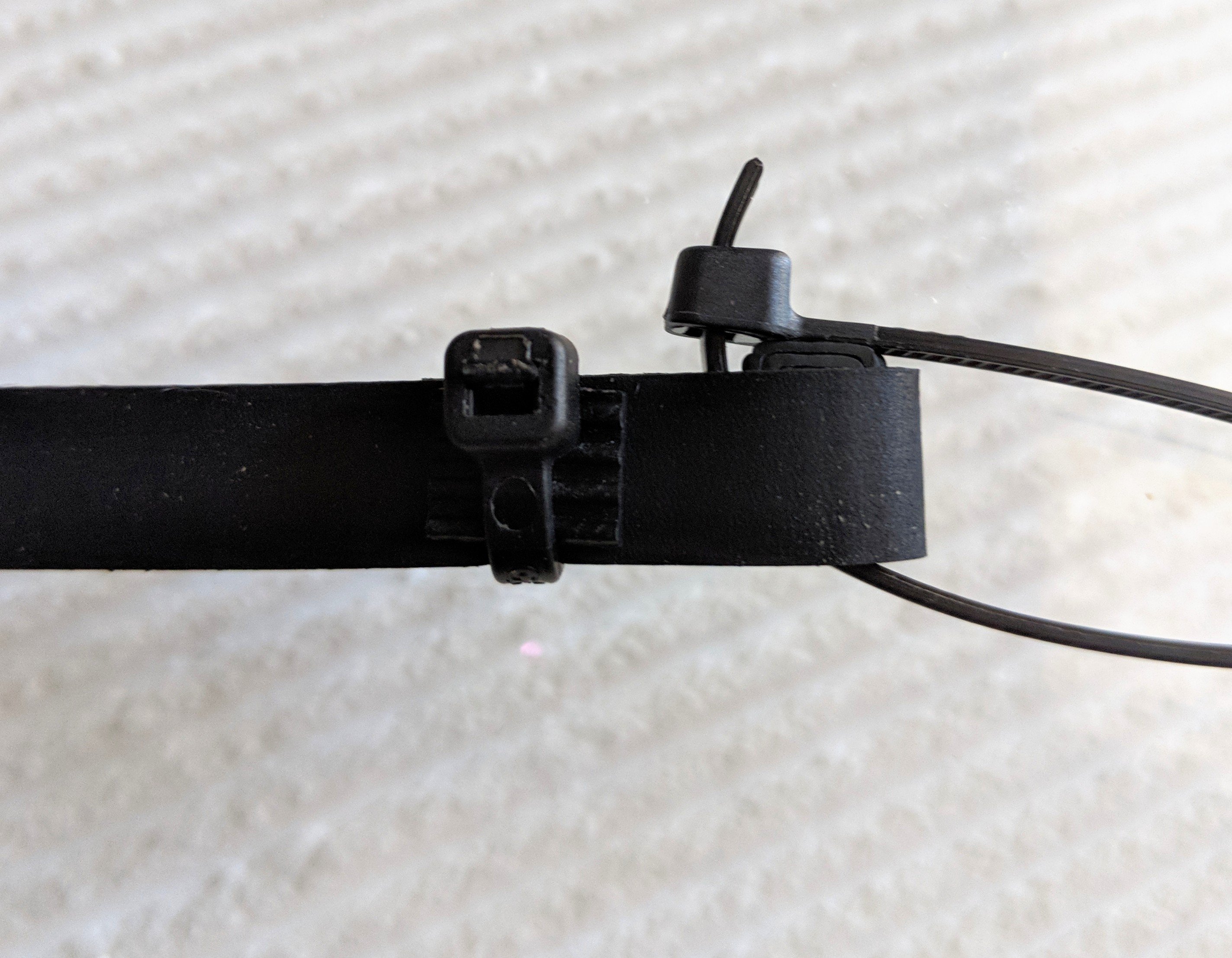
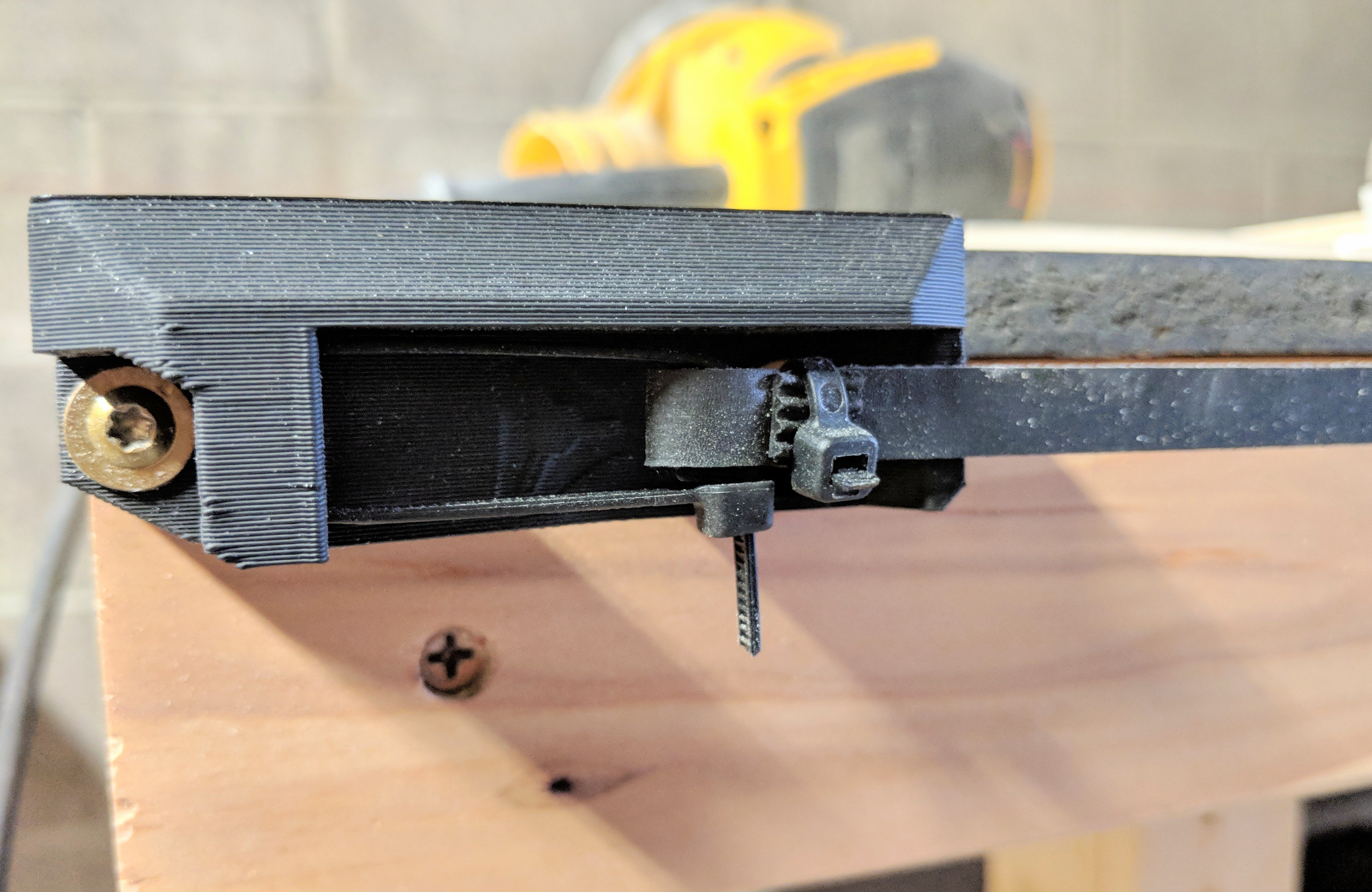
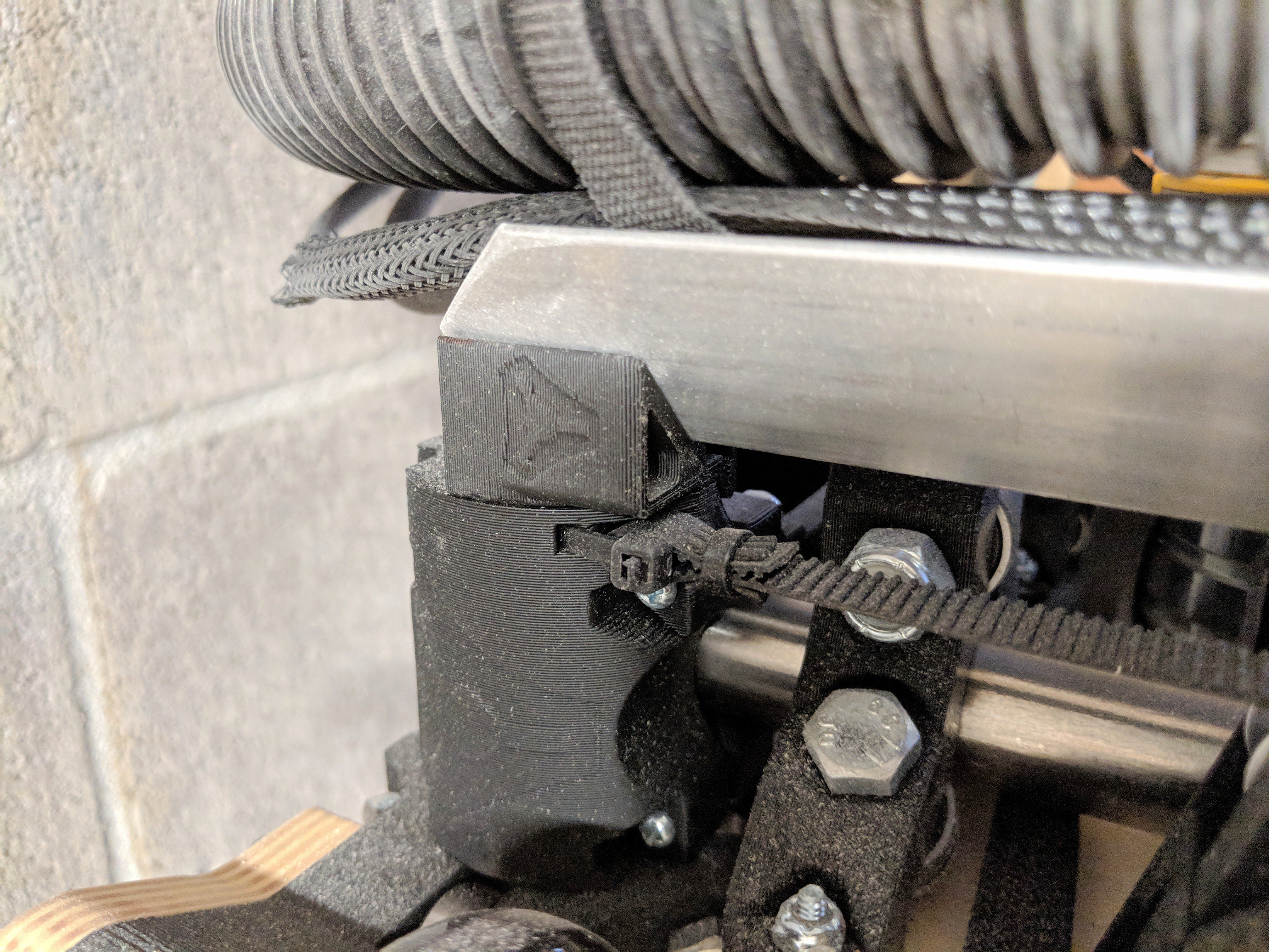
Belt Ends
Table
Use the dimensions from the calculator, make it as flat and square as you can. The edges guide the machine so those are important. I used some 2″x3″ and ½″ particle board on top.
The X direction is more important to get flat than the Y direction, so build accordingly. Usually this means solid supports in The X direction. If you can picture it the machine and material can follow a subtle curve down the length much more so than the width.
Note
Ideal table thickness is 4″ or less.
Firmware
The standard MPCNC firmware will work with any board on the LowRider2. Dual endstop firmware is not really needed since all three axis have hard stops you can use for alignment.
For the creative of you, you could use the dual end stop firmware for Y alignment or even Z (homing min or max).
Hose Channel
I use 1.5″-2″ aluminum angle with a few Velcro straps to keep the hose and cords contained. Bigger or smaller works depending on the hose size you use.
Getting Started
Using the machine.
1) Square it up. After mounting your work piece (making sure the mounting hardware is not going to interfere) I check to make sure the sides (Assemblies with the wheels on them) are the same distance from the nearest end. You can do this by making sure the wheels are hitting the stop blocks/belt mounts.
2) Double check. You only need to do this the first few times until you understand the machine. Use the LCD to control the machine. Lift the gantry high enough as to not drag the bit across your material. Drive the machine the entire length of what you will be cutting. This is to make sure the machine does not hit the table and you are parallel with it. Another way to do this is include an outline in your design and use it as your fist tool path above your material. This is to make sure nothing binds or hits.
3) Set your starting position. Use the lcd to position the bit at your zero position in all three axis.
4) Beginning gcode. If you use the Fusion 360 post processor this is done for you but make sure your
beginning gcode resets all your axis to 0,0,0, you can use this command, G92 X0 Y0 Z0.
5) Ending gcode. What should happen is your job ends above your last position, meaning your bit should not drag across the surface if you move it. With the bit above the last position, telling the machine to go back to the starting position will return the machine to where you started it and then making sure the steppers do not turn off is a good idea as the LowRider will drop under its own weight. The last few lines of your gcode should look like this.
G1 Z7 F400 (this is my clearance plane and is already in my gcode)
G1 X0 Y0 F2100 (I add this to have the machine drive itself back to the start)
At this point you can use the lcd to move the machine clear of your material and lower it, then power off.
Or, if you leave a little room you can drive past your starting point and lower automatically.
G1 Z7 F400 (already there)
G1 X-15 Y-15 F2100 (drive 15mm past your start)
G1 Z0 F400 (Lower the machine)
M84; Turn steppers off