Ultimachine Control Boards
by Ryan | Apr 11, 2017 | Hardware & Electronics, News & Updates, Uncategorized
Ultimachine Boards
Want to Buy one? Mini-RAMBo Here, RAMBo Here, Archim1 Here.
UltiMachine boards are extremely high quality and built as the refined updated Ramps 1.4 board. Meaning it is a more reliable board and it has been designed with more robust safety features built in (harder to destroy these boards by accident). Hopefully this will result in a more pleasant user experience for the newcomers to electronics. These boards are using trusted high quality components and assembled in the U.S. Johnny R from UltiMachine designed the original Ramps series of boards and these are the next generations from him and his team. There are many improved features including properly implemented drivers with more efficient heat transfer, replaceable fuses, isolated USB, more ports, More control from the firmware did I mention DIGI-POTS!!!.
The boards are more expensive than the current ramps boards but have no assembly required and I am expecting a nearly nonexistent failure rate (still true). These two factors mean I can have a much lower markup on them than the ramps. These boards also have the driver current that is set in the firmware meaning much less setup and testing time for me as well, again lowering the need for a steep markup and more accurate control over your steppers. The mini-Rambo has four drivers, this means no dual endstop firmware on this board without some skills and an external driver.
There is much more information available from UltiMachine or the Wiki links in each section.
Firmware
Looking for firmware?
The firmware details for all boards can be found HERE
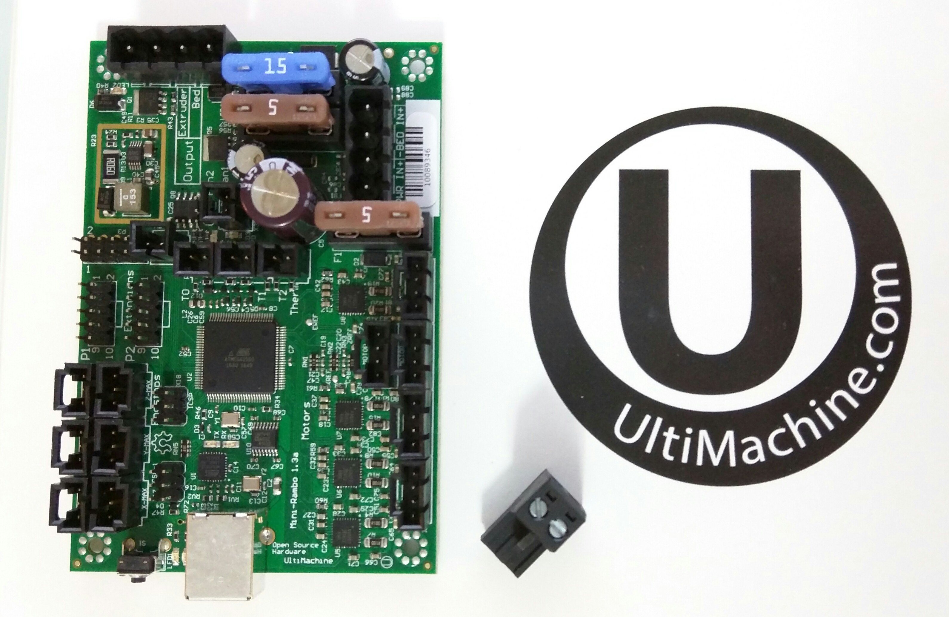
Mini Rambo
Shop link
All the Details you could need, http://reprap.org/wiki/MiniRambo
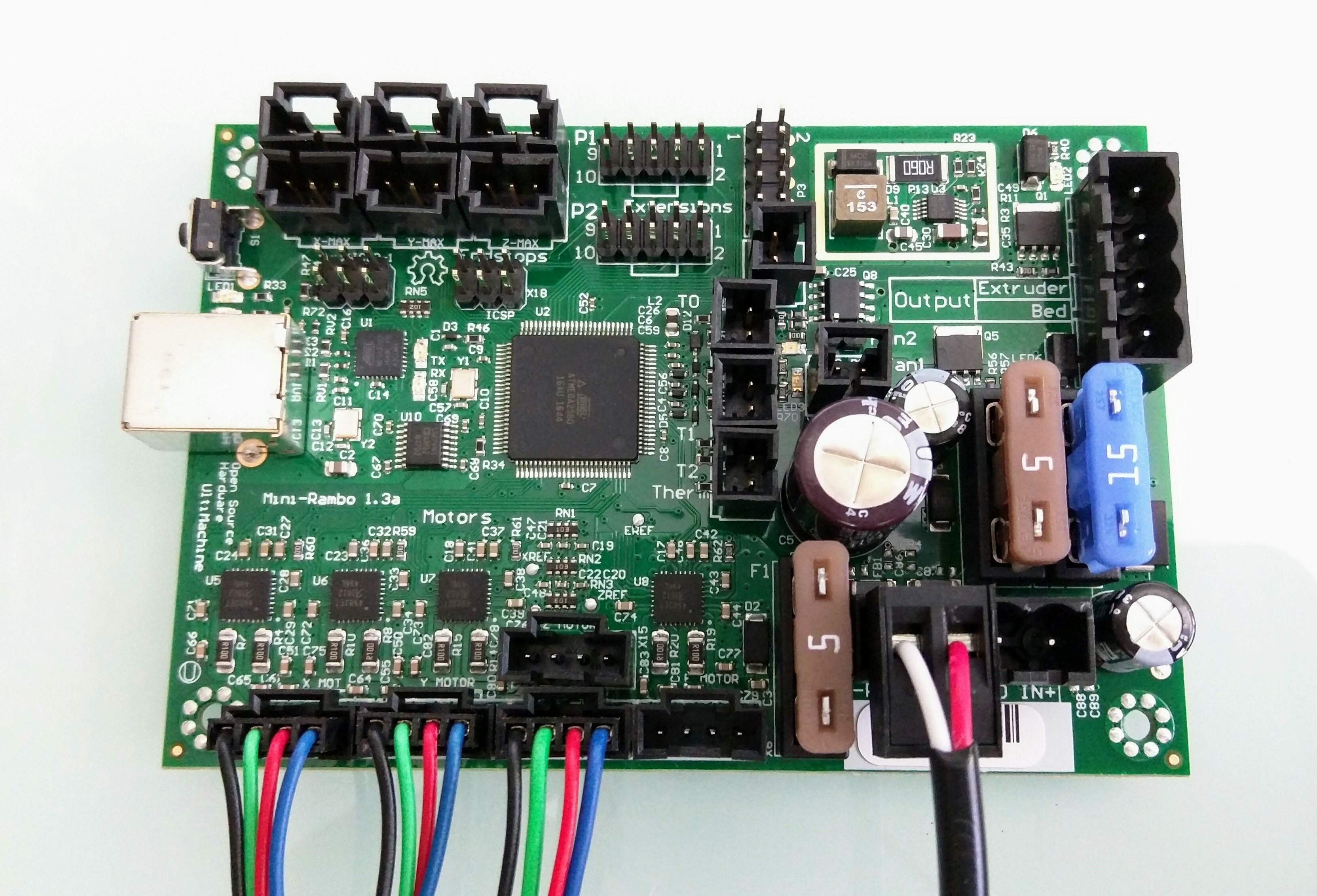
The most common way the Mini Rambo will be used on the Mostly Printed CNC or LowRider CNC, will just be power and the X, Y, and Z steppers. The board is labeled clearly on each port. (moving the wrong way?)
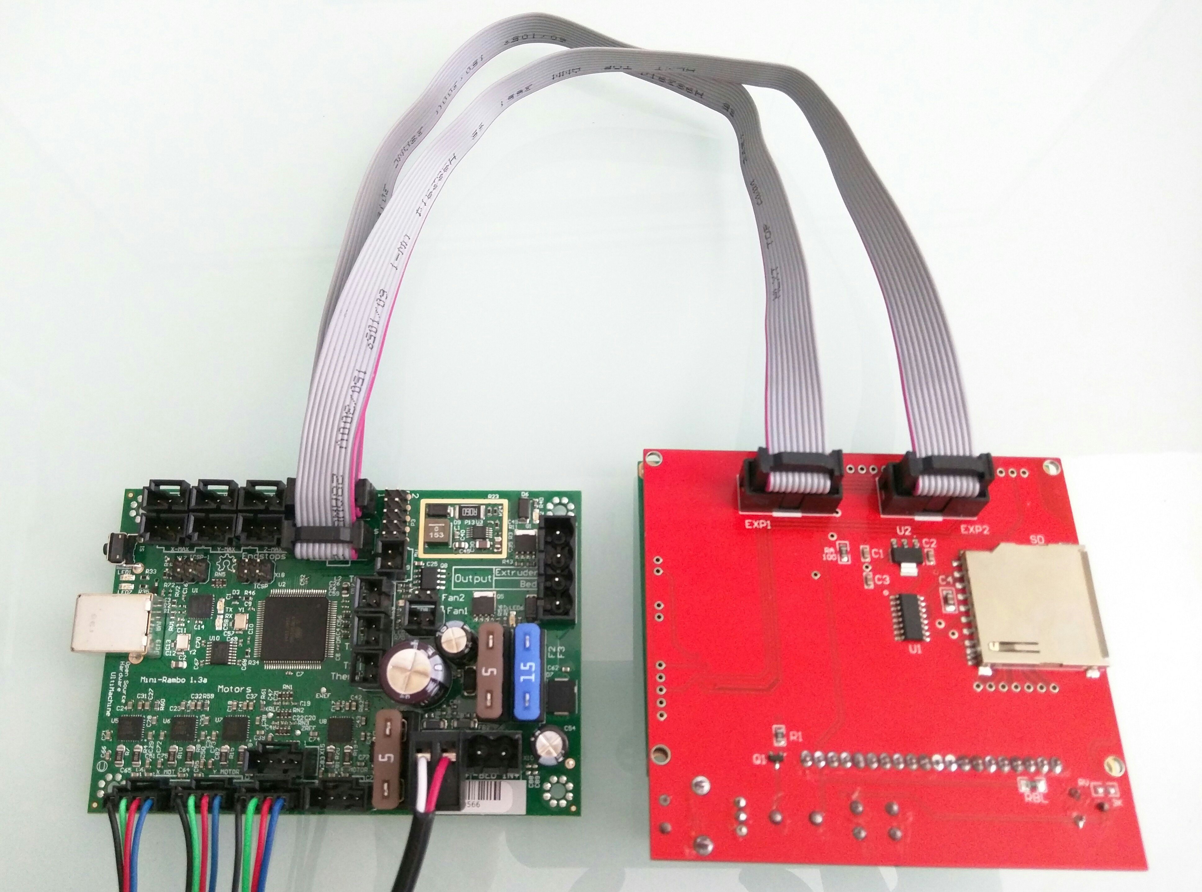
Adding an LCD
If you are using an LCD the header adapter is not needed and you can plug it directly into the board as shown.
Adding an Extruder
To use an extruder you will need to flash the extruder enabled firmware or set the firmware to your appropriate thermistor value (Most commonly 11). You will then need to plug in your extruder heater, Thermistor to port T0, your print fan to port fan 1, and your extruder stepper into E0.
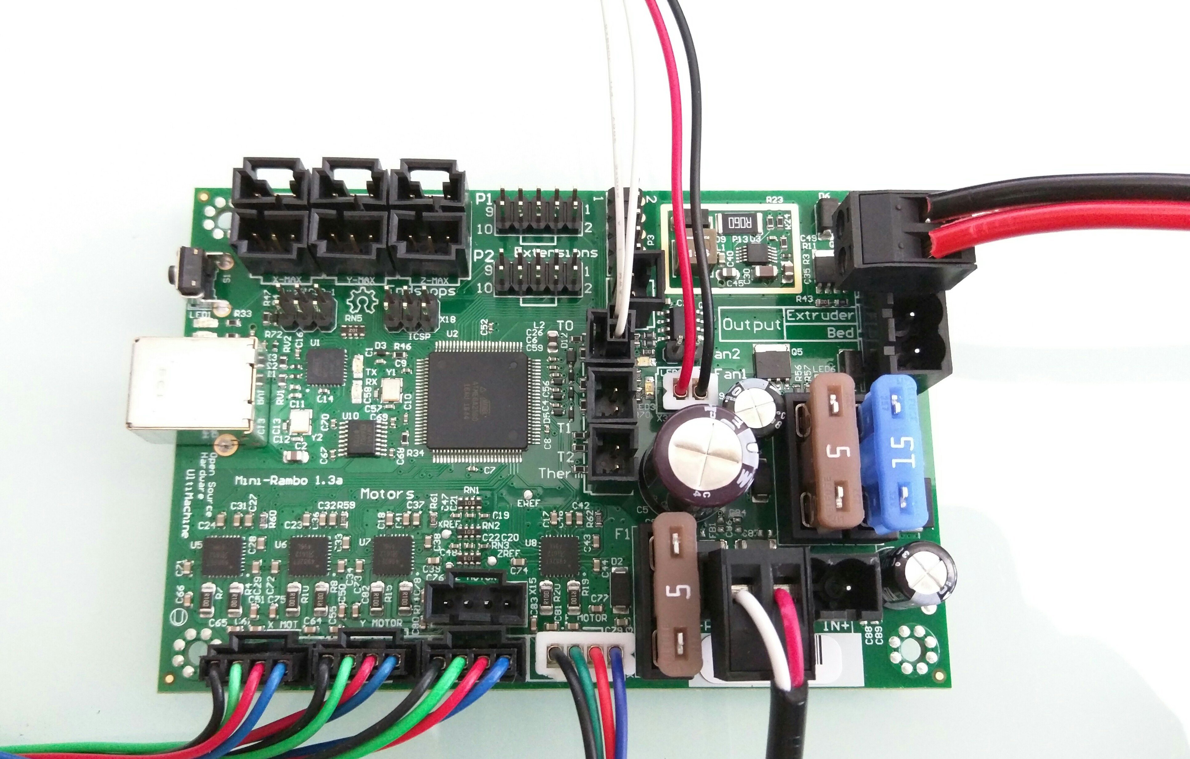
Adding a Heated Bed
In addition to all the wires above, you will need to add what is shown in the picture below. Everything else has been removed for clarity. The firmware will need to have the heated bed thermistor value set (Usually to 11). You will need to add the bed thermistor to port T1, power to both inputs A&B, and of course the bed plugs into the heated bed port.
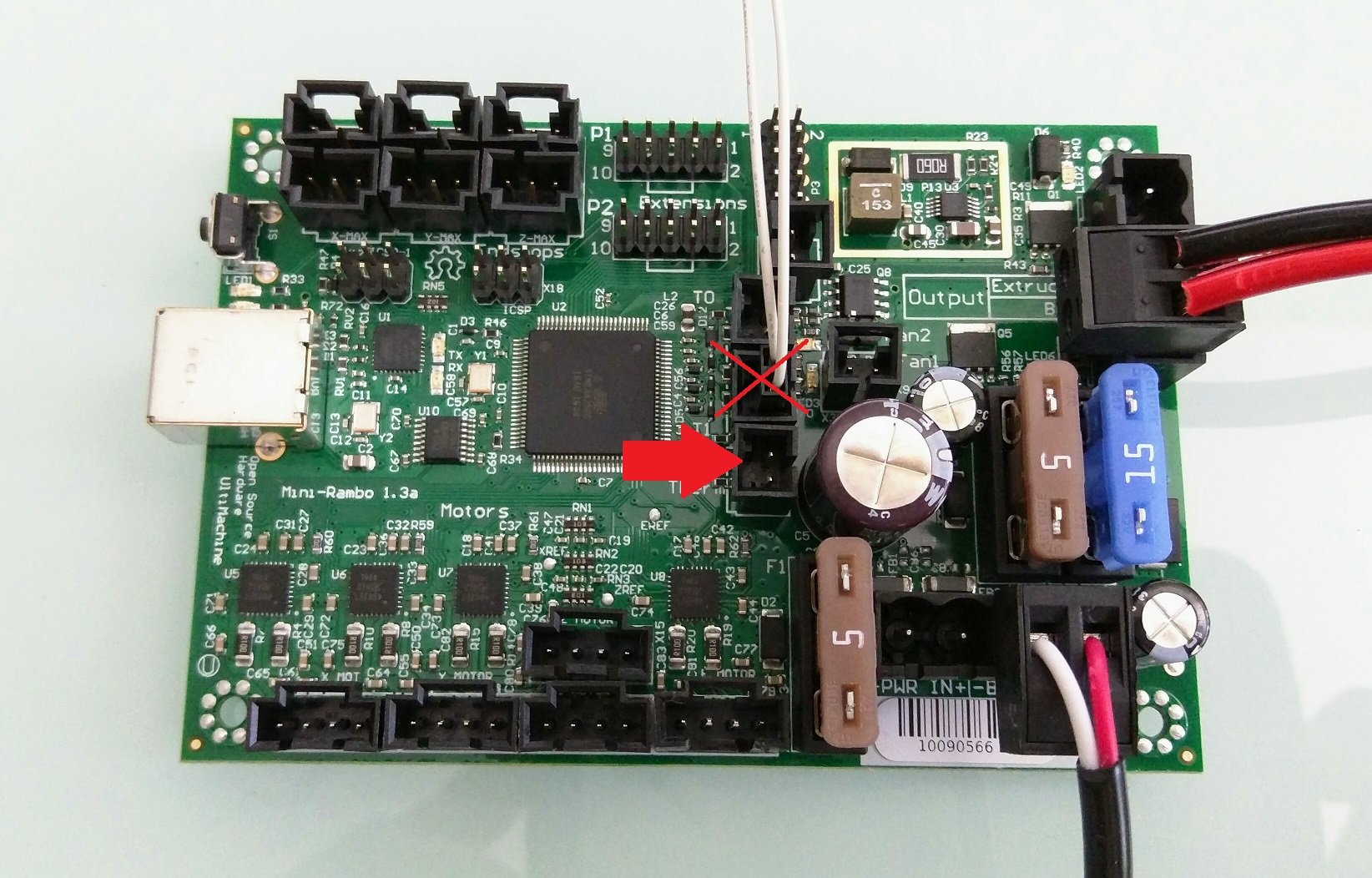
Warning
The port in this picture with the big arrow next to it should have your bed thermistor wires in it. Otherwise, it will just heat up forever.
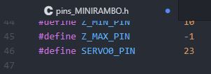
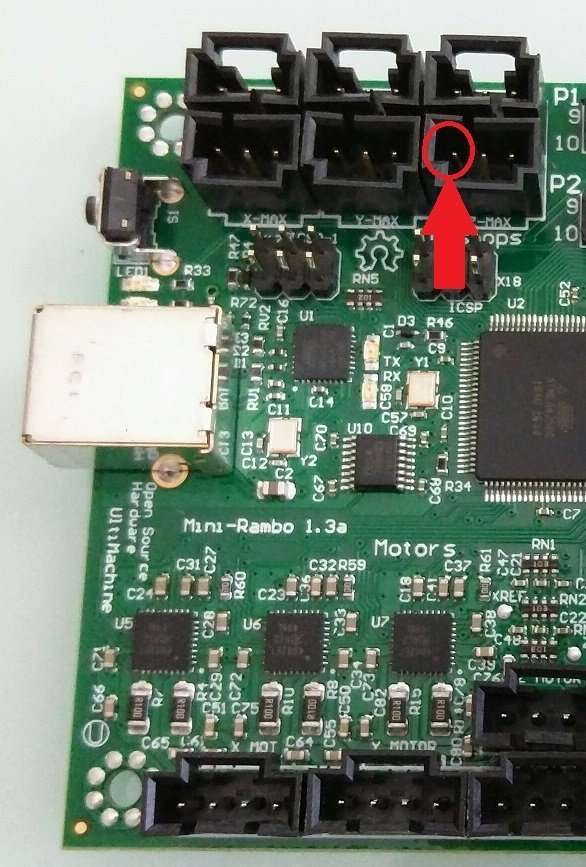
Adding a Laser Pin / BlTouch / Spare PWM
Pin 23 is the signal pin for the ZMax endstop it is PWM capable and usually unused. For the BLTouch
you will need to designate it for a “servo”.
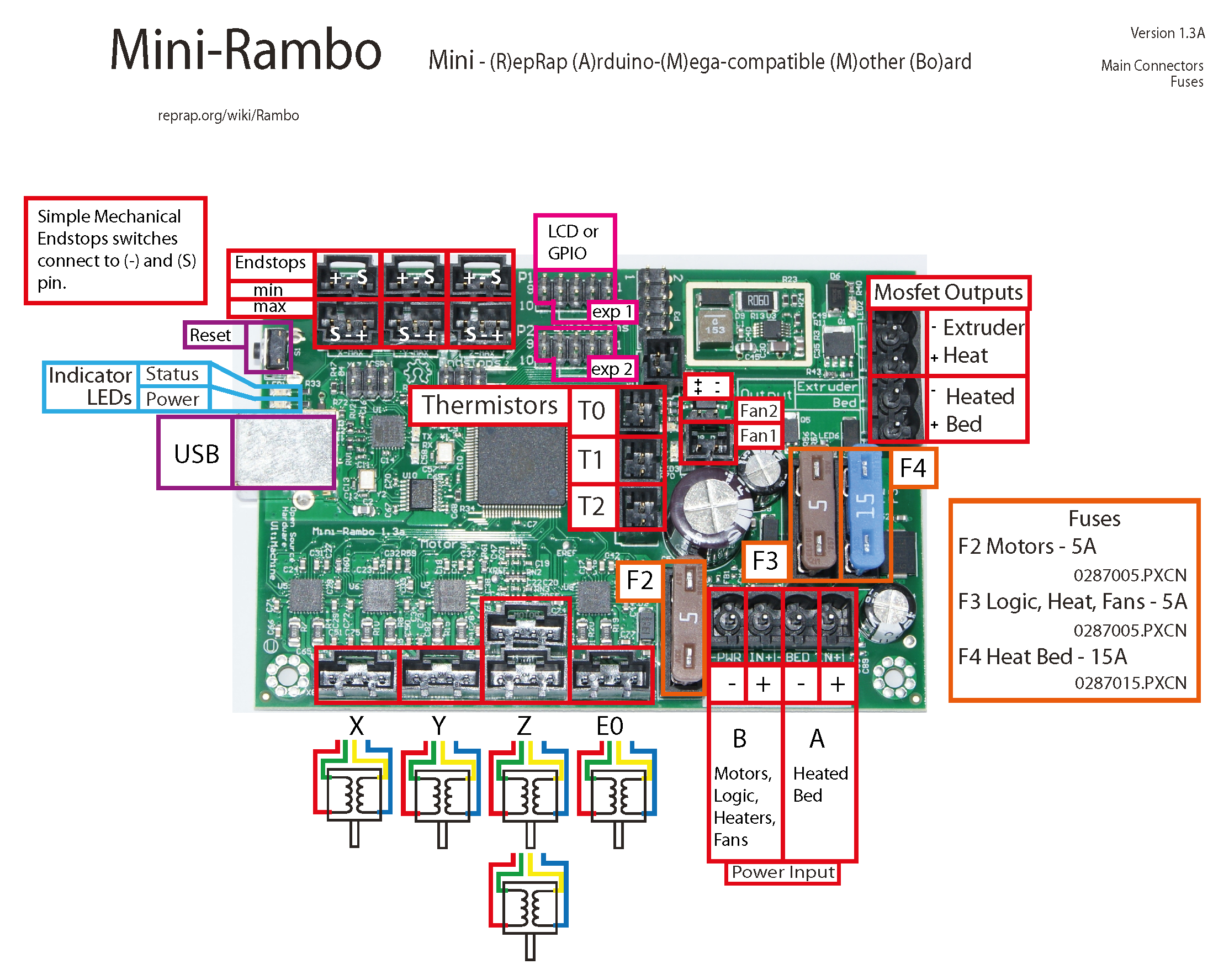
Formal Details
If you have any doubts or are unclear on anything the wiki page should have all your answers. http://reprap.org/wiki/File:MiniRambo1.3a-connections.png
Driver Math
These can now be set in Configuration_adv.h
#define PWM_MOTOR_CURRENT {950, 950, 950} //XY,Z,E
Bonus
Connectors/Plugs
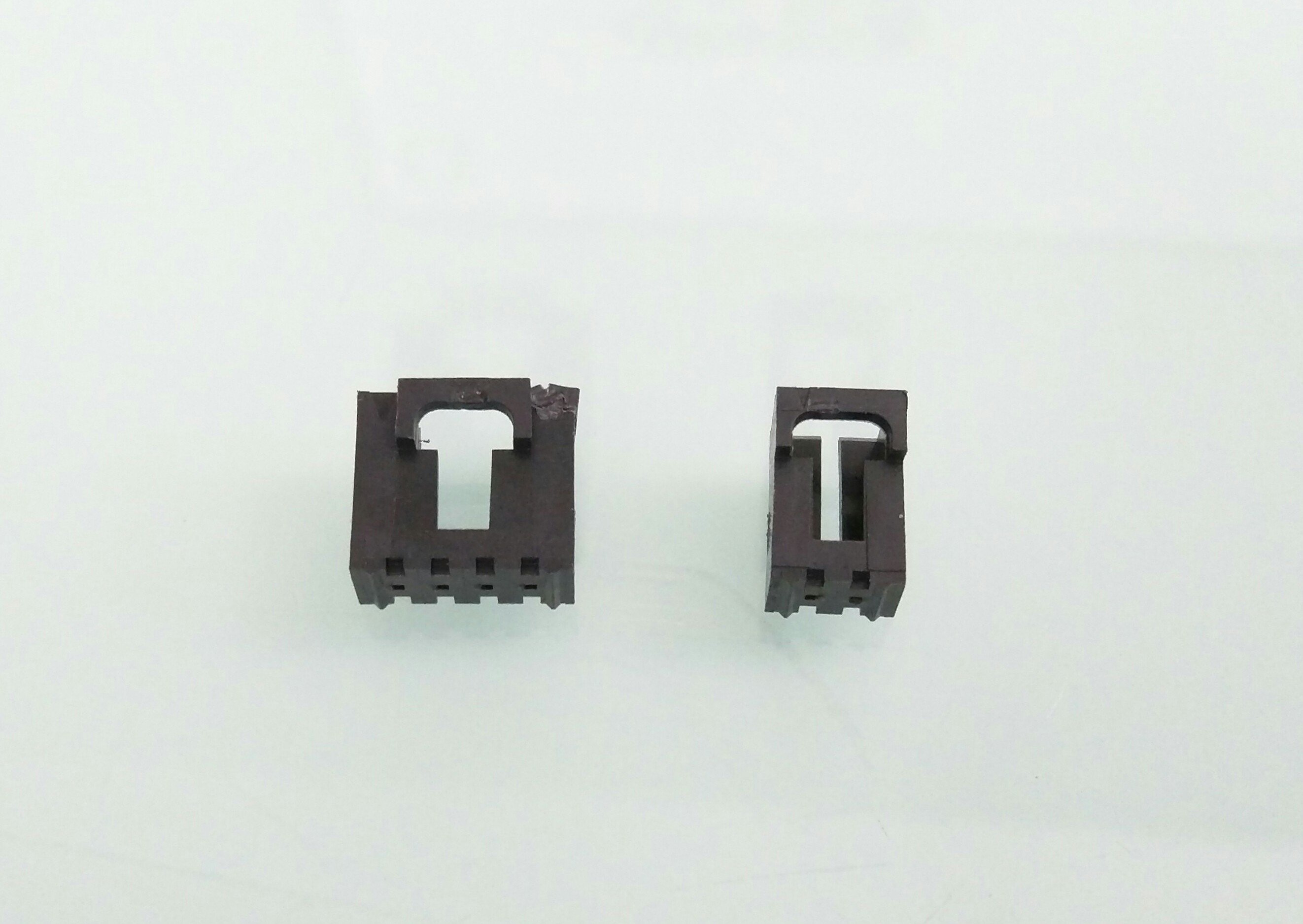
If you have plugs that do not fit the sockets on the Mini Rambo, you can persuade them to come off and usually your plugs will fit the bare pins.
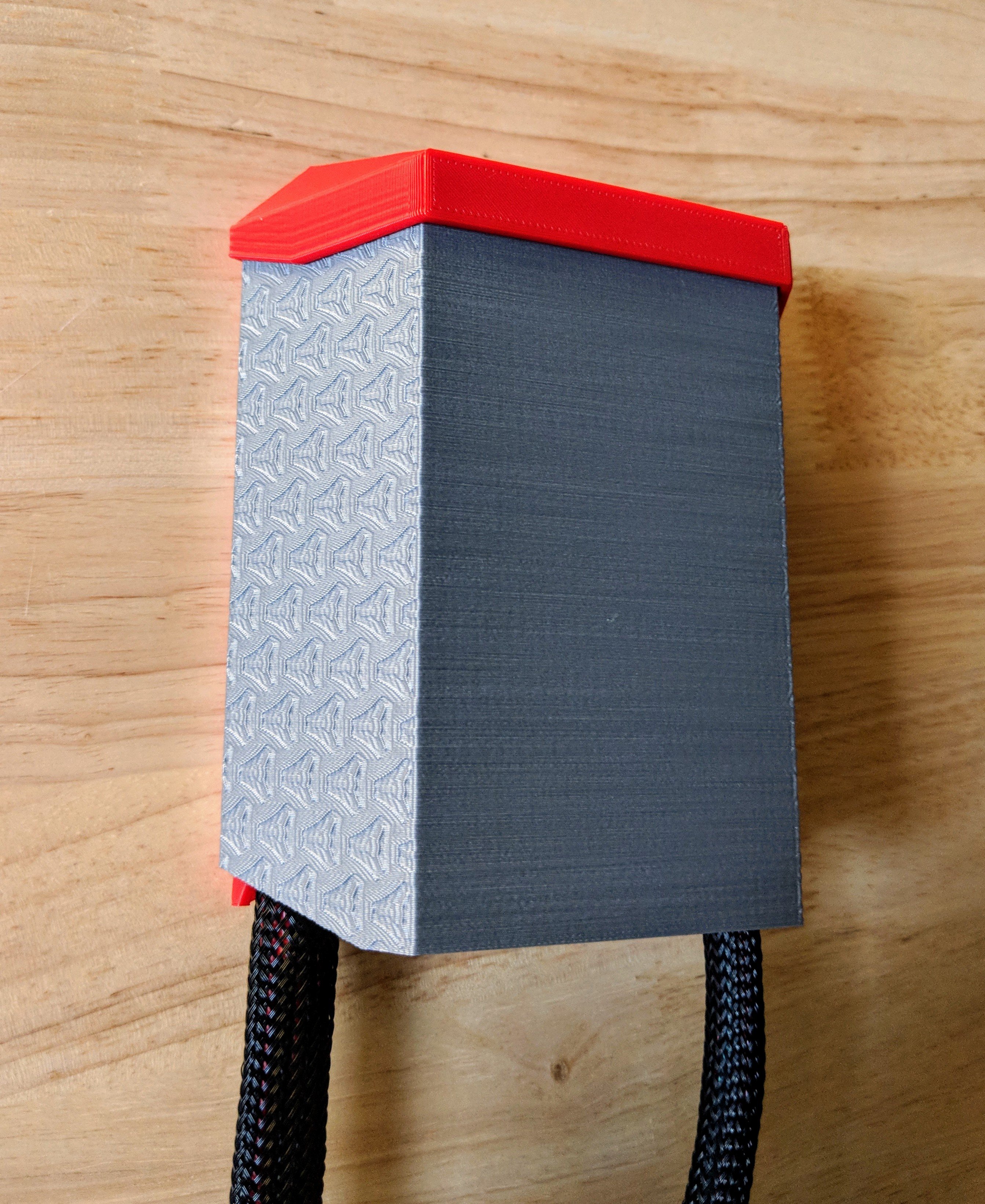
Case
Need a fancy Box for your fancy board?
Dual End Stop
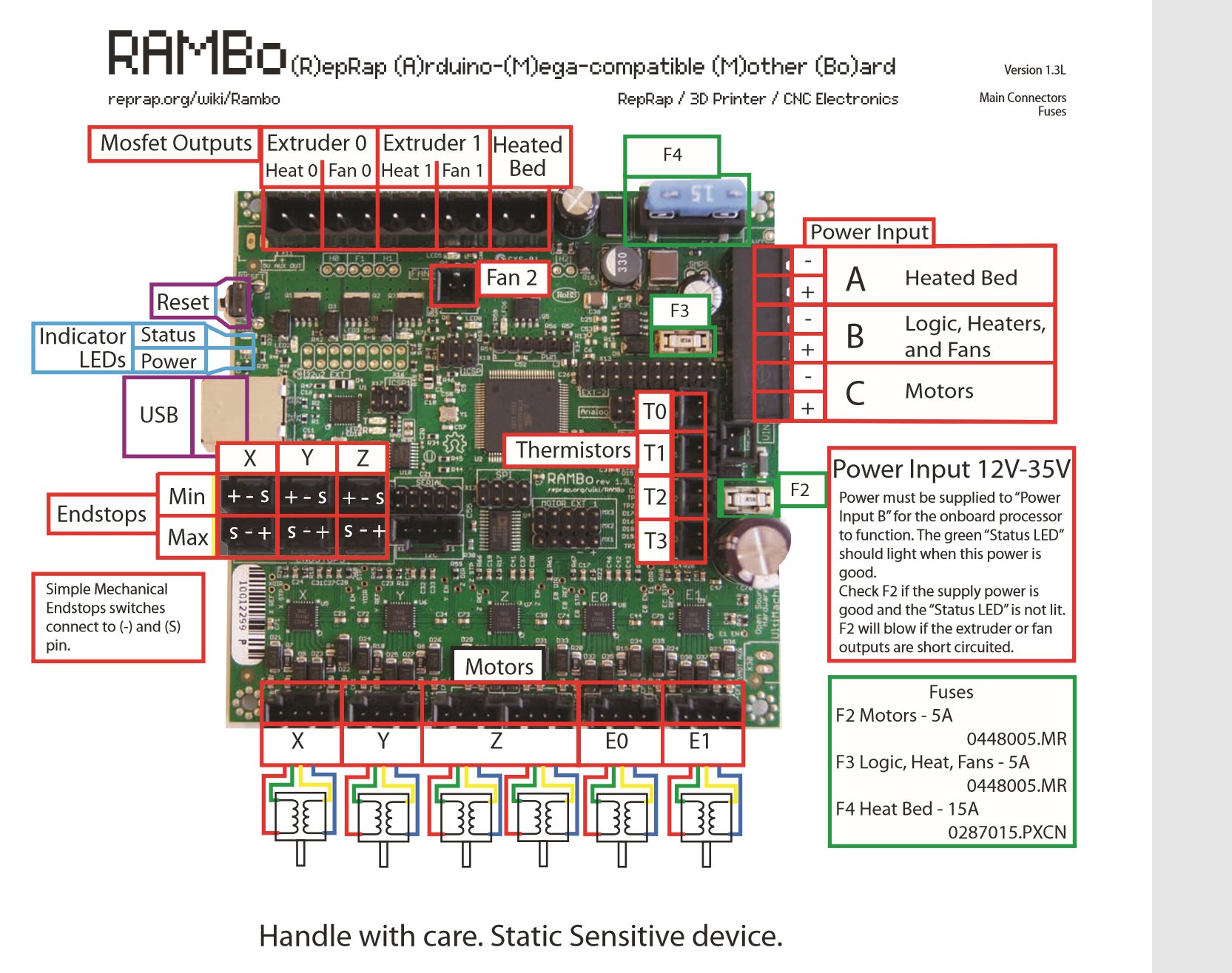
Rambo 1.3 -1.4
Shop link
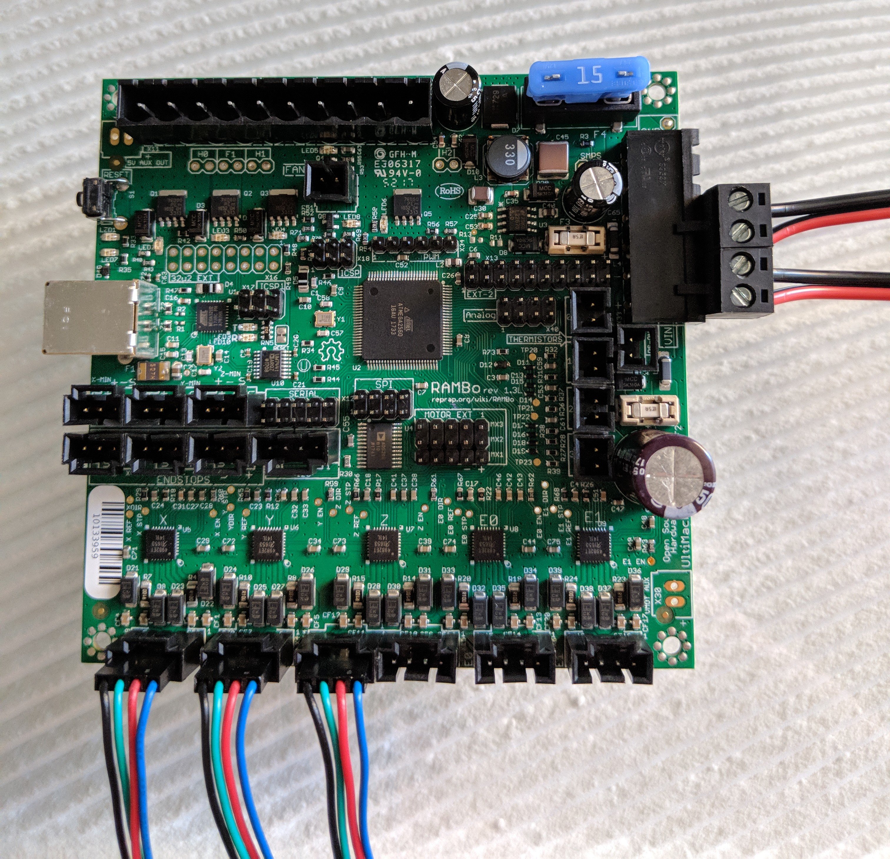
The most common way the Rambo will be used on the Mostly Printed CNC or LowRider CNC is to plug in the X, Y, and Z steppers. Then you need power to both the logic and stepper circuits.
MPCNC dual endstop wiring.
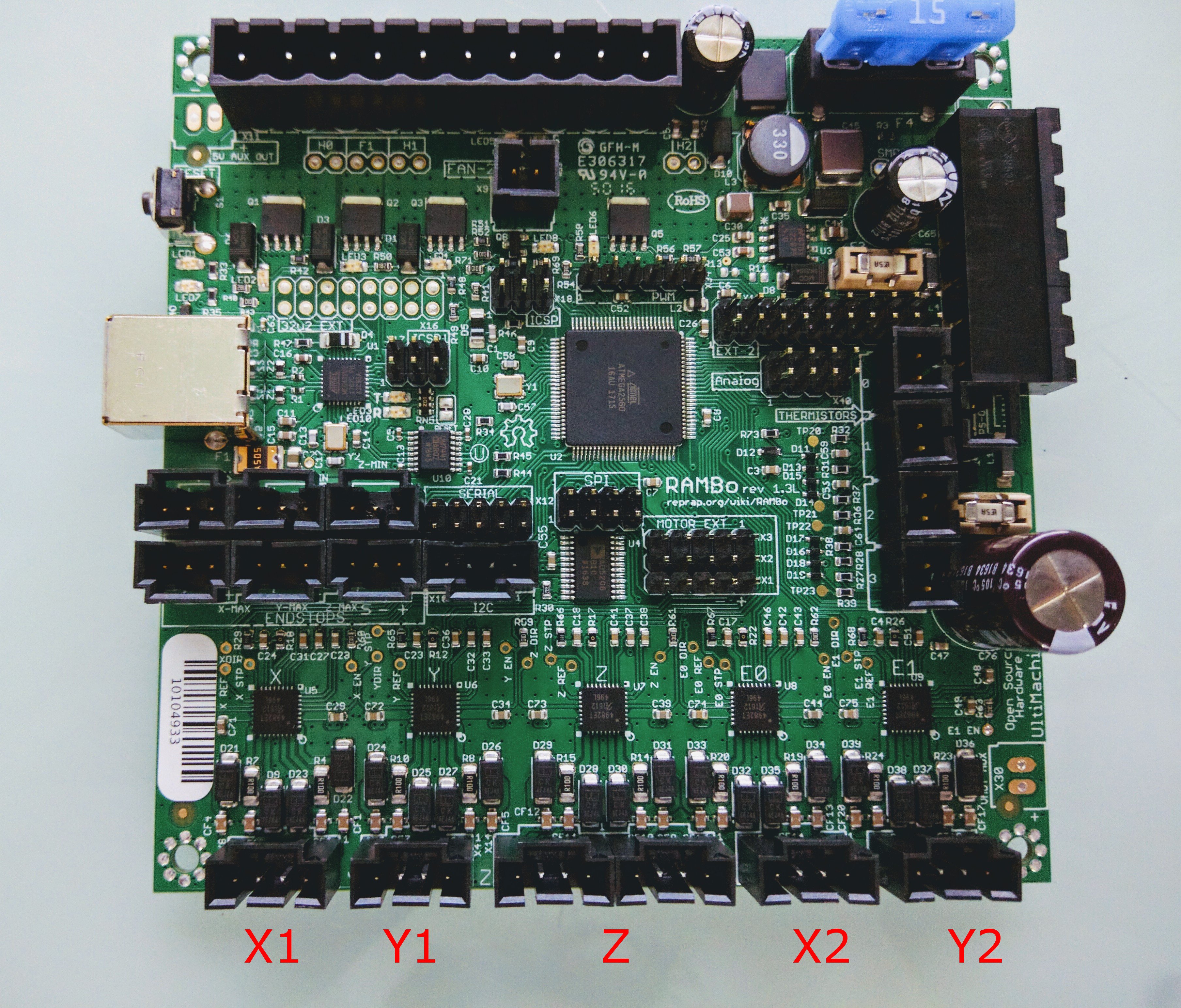
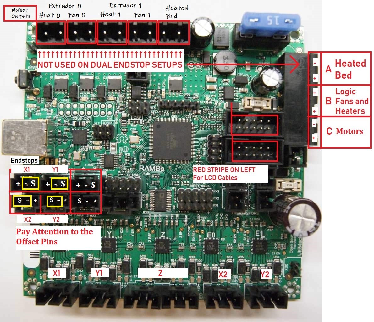
Pay attention the endstop pins are opposite each other, but clearly labeled on the board. For the safest configuration the endstops should be wired in the Normally Closed position (NC), to prevent wire disconnects from damaging the machine during the homing sequence.
Mechanical endstops are connected to the signal and ground pins filtered or optical endstops use all three pins, connect these with extreme caution. Using the wrongs pins will damage your control board.
Optical endstops are not recommended on a machine used for milling or routing. The debris can inhibit there function.
All the Rambo details in their full glory, https://reprap.org/wiki/Rambo_v1.4
Power
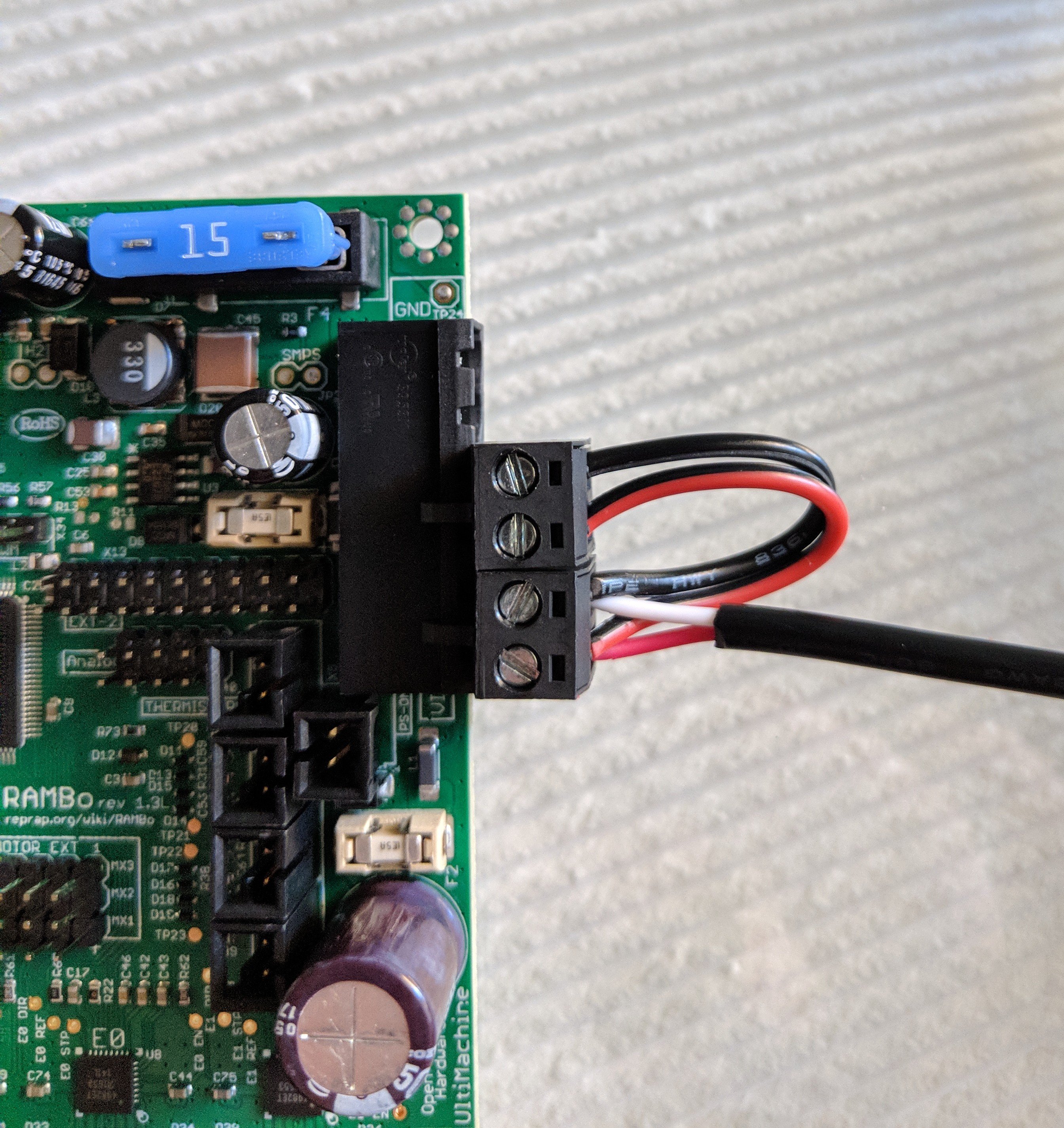
You can add a Short jumper to get power to both ports, mind the polarity. The board does have labels but the Diagram below should be a little clearer.
Best practice not to use any adapters. If your power supply has a barrel jack you can cut it off and wire it up directly, again double check the polarity, some red and white wires are opposite of what you would expect.
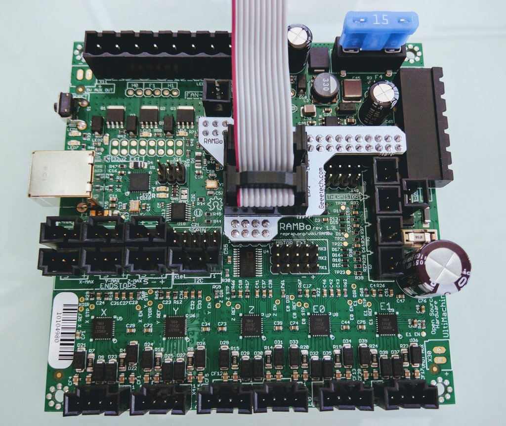
Adding an LCD
Rambo 1.4
The Rambo 1.4 no longer needs an adapter but the first batch have shrouded pins (custom un-shrouded 1.4’s are on the way). This means some of the LCD cables will be backwards… Easy fix here.
Rambo 1.3
Using an LCD requires an adapter on the full sized Rambo 1.3.
Adding a Laser Pin
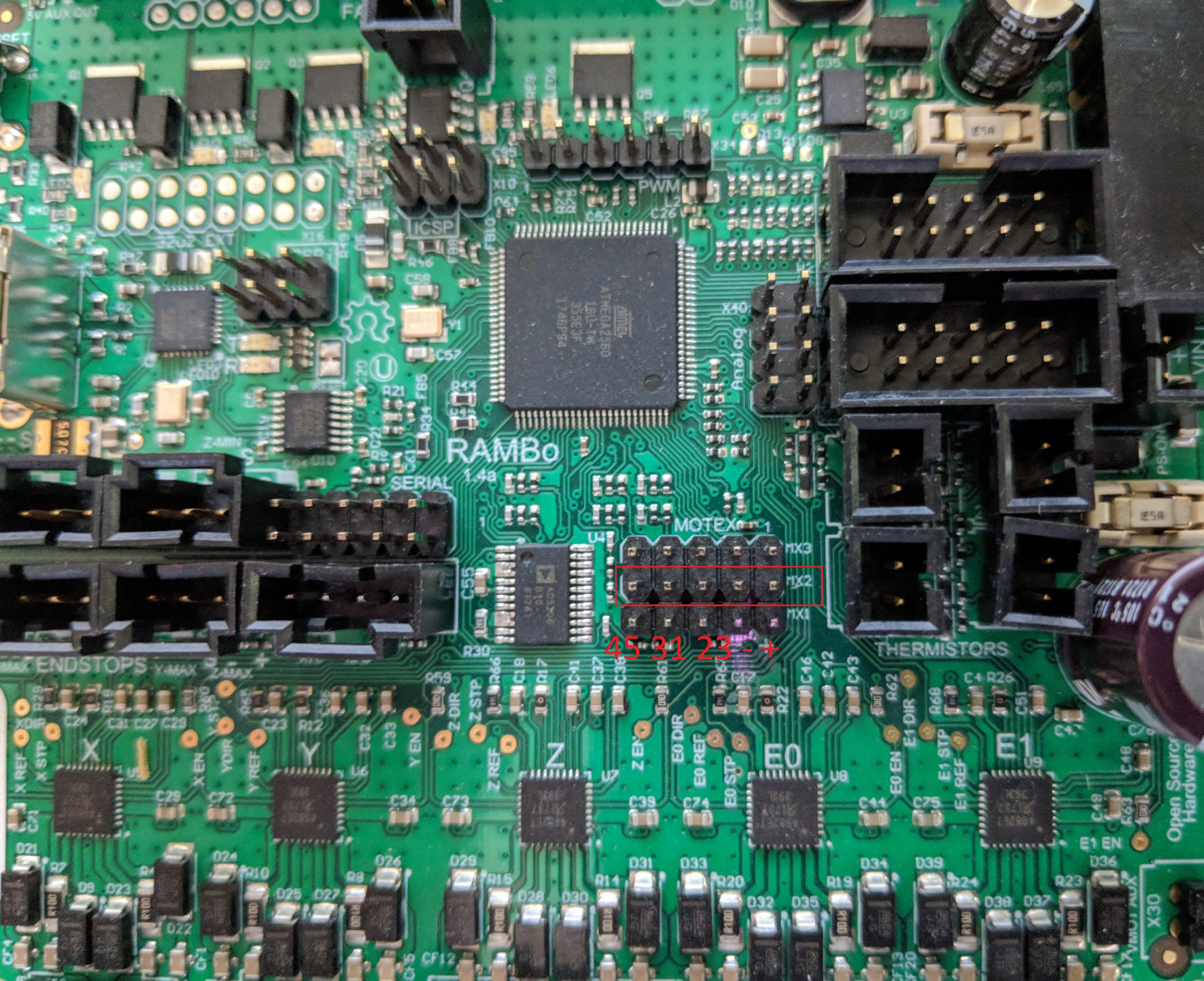
When using a laser or a PID controller the Pins on MX2 are available:
- 45 (PWM)
- Your laser pin or PID speed. Controlled by
M3 - 31 (Laser or PID)
- Enable, Controlled by
M5 - 23 (not assigned yet)
- Shared with Y_{MAX}
Details
Driver Math
These can now be set in Configuration_adv.h
- I_{Trip}^{MAX}
- Max Current. As stated Setting the drivers to 70%-90% of max rated amps is a good idea (70% seems pretty good to me.)
- V_{Ref} = I_{Trip}^{MAX} * 0.8
- Reference Voltage for the driver. This gives you the ideal test point voltage.
- W_v = (V_{Ref} / 1.66) * 255
- The PWM value needed (if you are using a rambo stop here I believe))
// Motor current PWM conversion, PWM value = MotorCurrentSetting * 255 / range
#define MOTOR_CURRENT_PWM_RANGE 2000
#define DEFAULT_PWM_MOTOR_CURRENT  {900, 900, 900}
DEFAULT_PWM_MOTOR_CURRENT= Wv/255*2000- Values are XY, Z, E
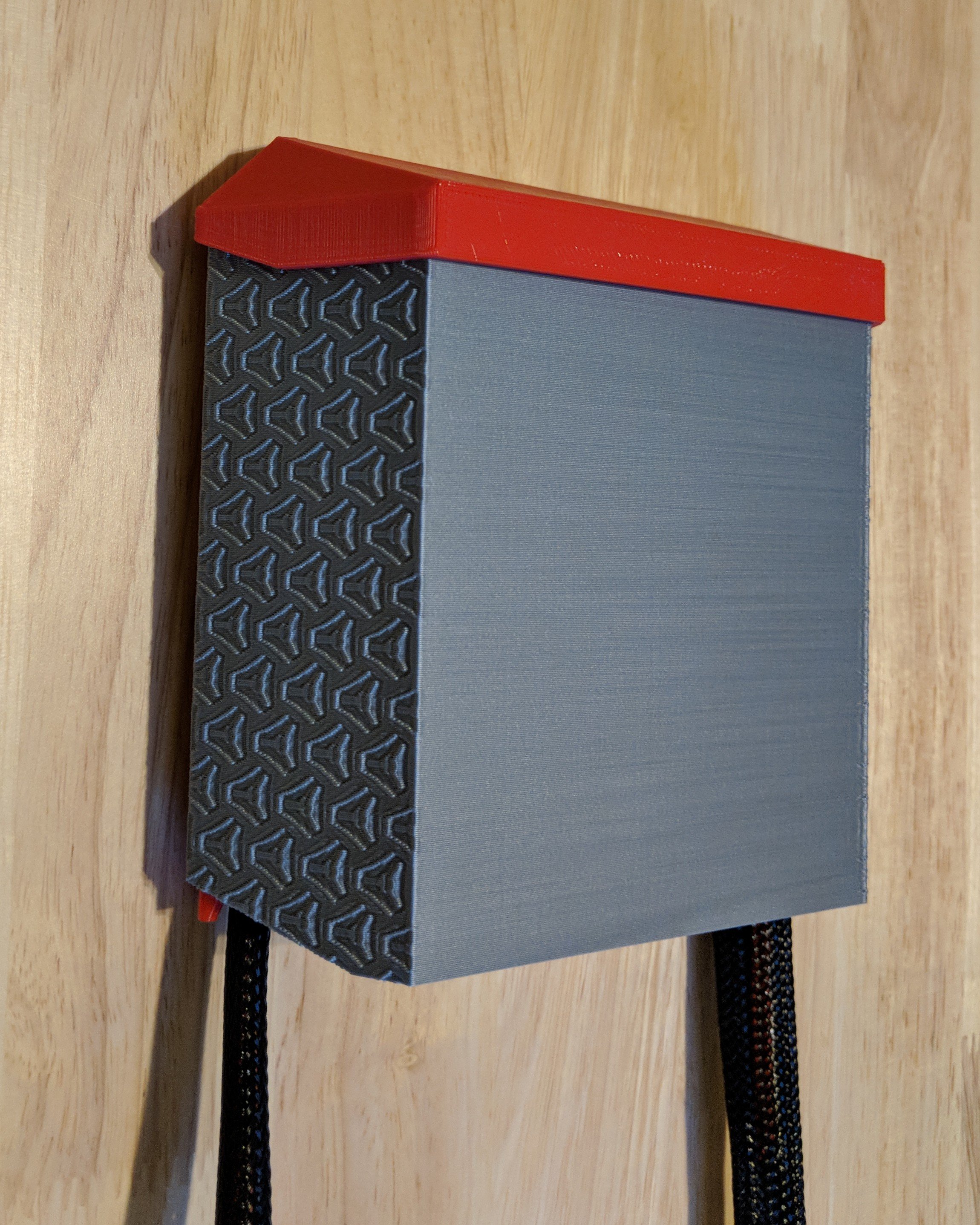
Case
Need a fancy Box for your fancy board?
Dual End Stop
Archim
Shop link
Wiki links, Archim 1 & Archim 2
Before you ask, the only difference is the Archim 2 uses Trinamic drivers. This is setup up extremely similar to the Rambo board except no LCD adapter is needed.
Case
Need a fancy Box for your fancy board?